Your PC will not boot. Your car’s dashboard warning lights refuse to turn off. A homemade circuit board does nothing when you power it on.
All three problems start the same way — with a multimeter. This advanced guide covers how to test a computer motherboard, an automotive ECU, BCM, or TCM, a general PCB, and how to properly evaluate cold cranking amps (CCA) on a battery.
This guide assumes you already know the basics of using a multimeter. If you need a refresher first, check out our How to Use a Multimeter guide before continuing.
Safety Precautions Before You Start
Testing motherboards, control modules, and circuit boards involves sensitive electronics. Skipping safety steps is the fastest way to damage a board that was actually fine.
Discharge Static Electricity (ESD Protection)
Static electricity from your body can destroy sensitive chips instantly — even if the board looks completely fine afterward. Wear an anti-static wrist strap connected to a grounded metal surface, or at minimum touch a grounded metal object before handling any board.
Power Down and Discharge Capacitors
Turn off and unplug the device completely before any resistance or continuity testing. Press the power button once after unplugging to discharge any remaining energy in the power supply. Large capacitors on motherboards and power boards can hold a charge even after the power is removed.
⚠️ Warning: Never measure resistance or continuity on a powered board. The multimeter sends its own small test current — external voltage interferes with the reading and can blow the internal fuse or permanently damage the meter.
What You Need Before Testing
- A digital multimeter with DC voltage, resistance, continuity, and diode test modes
- Fine-tipped test probes for reaching small pins and solder joints
- Anti-static wrist strap or grounding mat
- A schematic or pinout diagram if available
- Good lighting and a stable, clean workspace
Visual Inspection Checklist
Before touching your multimeter, look the board over carefully. Many faults are visible without any electrical testing at all.
| Check | What to Look For |
|---|---|
| Capacitors | Bulging tops, leaking fluid, discoloration |
| Solder joints | Cracked, dull, or cold-looking joints |
| Traces | Burn marks, scorching, visible breaks |
| Connectors | Loose pins, corrosion, bent contacts |
| General surface | Burnt smell, melted plastic, discoloration |
How to Test a Motherboard with a Multimeter
Step 1: Check the CMOS Battery
A dead CMOS battery is one of the most common and easiest to fix motherboard problems. It causes BIOS settings to reset, the system clock to lose time, or in some cases prevents booting entirely.
- Locate the small coin-shaped battery on the motherboard (usually a CR2032)
- Set your multimeter to DC voltage mode on the 20V range
- Touch the red probe to the top (positive) of the battery
- Touch the black probe to the metal battery holder or a ground point
- Read the voltage
| Reading | What It Means |
|---|---|
| 3.0V or above | Battery is healthy |
| 2.8V to 3.0V | Battery is weak — replace soon |
| Below 2.8V | Battery is dead — replace immediately |
Step 2: Test the ATX Power Rail Voltages

With the motherboard connected to the power supply and turned on, carefully back-probe the connector by touching the red lead to each colored power wire and the black lead to a black ground wire.

ATX Voltage Rail Results Table
| Rail | Wire Color | Acceptable Range | Bad Reading |
|---|---|---|---|
| +12V | Yellow | 11.4V to 12.6V | Below 11.4V or above 12.6V |
| +5V | Red | 4.75V to 5.25V | Below 4.75V or above 5.25V |
| +3.3V | Orange | 3.14V to 3.47V | Below 3.14V or above 3.47V |
If any rail falls outside its range, the issue is most likely the power supply, not the motherboard itself. Check out our How to Test a PSU with a Multimeter guide to confirm.
Step 3: Check for Short Circuits
Power the board down and unplug it completely before this test. A motherboard short often causes the classic “one-second start”: fans spin briefly, then the system immediately loses power, along with a burnt smell or complete unresponsiveness.
- Set your multimeter to continuity mode
- Touch one probe to a known ground point (metal USB port shell or a ground pin on the 24-pin connector)
- Touch the other probe to the suspected power rail or component
- Listen for the result
| Result | What It Means |
|---|---|
| No beep, high resistance | No short at this point: normal |
| Continuous beep or near 0Ω | Short circuit present |
A short at the 12V CPU power pins (4-pin or 8-pin EPS connector) near the processor socket often points to a failed MOSFET in the voltage regulator module (VRM). This level of repair usually requires professional micro-soldering equipment.
Step 4: Test the Motherboard Capacitors
- Set your multimeter to resistance mode (Ω)
- Touch one probe to each capacitor leg
- Watch how the reading behaves over a few seconds
| Reading Behavior | What It Means |
|---|---|
| Starts low, rises steadily toward infinity | Healthy capacitor |
| Stuck at 0Ω | Capacitor is shorted; replace it |
| Immediately shows OL | Capacitor may be open |
| Bulging or leaking regardless of reading | Replace it visual damage overrides the reading |
💡 Note: A standard multimeter cannot measure Equivalent Series Resistance (ESR), which is the most reliable indicator of capacitor health. A capacitor that reads normally on resistance mode can still have failed ESR. If you suspect capacitor issues on multiple boards, an ESR meter is a worthwhile investment.
Motherboard Test Results Summary Table
| Test | Healthy Result | Faulty Result |
|---|---|---|
| CMOS battery | 3.0V or above | Below 2.8V |
| +12V rail | 11.4V to 12.6V | Outside range |
| +5V rail | 4.75V to 5.25V | Outside range |
| +3.3V rail | 3.14V to 3.47V | Outside range |
| Short circuit test | No beep | Continuous beep or near 0Ω |
| Capacitor test | Rising resistance | Stuck at 0Ω or immediate OL |
How to Test an ECU, BCM, or TCM with a Multimeter
What Is an ECU, BCM, and TCM?
ECU (Engine Control Unit): Manages engine functions, fuel injection, ignition timing, and emissions control.
BCM (Body Control Module): Manages body electronics: lights, power windows, locks, and interior comfort features.
TCM (Transmission Control Module): Manages automatic transmission shifting and torque converter lockup.
All three are essentially specialized computers, and they share testing principles with any circuit board — power supply, ground reference, and communication signals must all be verified.
Safety Precautions for Automotive Module Testing
Always disconnect the vehicle battery negative terminal before removing or handling a control module. Modern vehicle electronics are extremely sensitive to static discharge and incorrect voltage. Never probe module connectors with the ignition on unless specifically testing live signals, and always confirm correct polarity before connecting any probe.
Step 1: Test Power and Ground Circuits
- With the connector disconnected from the module, set your multimeter to DC voltage mode
- Turn the ignition to the ON position (engine off)
- Identify the main power pin using the wiring diagram for your vehicle
- Touch the red probe to the power pin and the black probe to a known chassis ground
- Read the voltage — it should be close to battery voltage (12.6V or higher with a healthy battery)
Then test the ground circuits using continuity mode with the battery disconnected. Touch one probe to each ground pin and the other to chassis ground. You should hear a beep confirming a solid ground path.
Step 2: Test Communication Bus Voltage (CAN Bus)
Most modern ECUs, BCMs, and TCMs communicate over a CAN bus using two wires: CAN High and CAN Low.
- With the ignition on and the system at rest (no active diagnostic communication), set your multimeter to DC voltage mode
- Touch the red probe to the CAN High wire and the black probe to chassis ground
- A healthy resting CAN High reading is close to 2.5V
- Repeat for CAN Low; it should also read close to 2.5V at rest
| Reading | What It Means |
|---|---|
| CAN High and CAN Low both near 2.5V | Bus is idle and healthy |
| 0V on either wire | Broken wire or module not communicating |
| Voltage stuck high or low | Possible short to power or ground on the bus wire |
💡 Tip: A standard multimeter cannot decode CAN bus data — it can only confirm the wires are present and at the expected resting voltage. Diagnosing actual communication errors requires an oscilloscope or a dedicated CAN bus analyzer.
Step 3: Test Sensor Input and Output Signals
Many ECU, BCM, and TCM faults trace back to a failed sensor feeding bad data into the module rather than the module itself.
- Identify the sensor signal wire using the wiring diagram
- Set your multimeter to DC voltage mode
- With the ignition on, back-probe the signal wire at the module connector
- Compare the reading to the expected value in the service manual (many sensors output between 0.5V and 4.5V depending on their state)
ECU/BCM/TCM Test Results Table
| Test | Healthy Result | Faulty Result |
|---|---|---|
| Power supply pin | Close to battery voltage (12.6V+) | Significantly low or 0V |
| Ground continuity | Beep solid connection | No beep broken ground |
| CAN High (resting) | Close to 2.5V | 0V or stuck high/low |
| CAN Low (resting) | Close to 2.5V | 0V or stuck high/low |
| Sensor signal | Matches service manual spec | Significantly outside spec |
How to Test a PCB with a Multimeter
Step 1: Test Continuity on Traces
- Power off and disconnect the board completely
- Set your multimeter to continuity mode
- Place one probe at the start of the trace and one probe at the end
- Listen for the beep
A beep confirms the trace or path is intact. No beep means the trace is broken, often from a hairline crack, poor etching, or physical damage.
Step 2: Check for Short Circuits Between Power and Ground
- With the board completely powered off, set your multimeter to continuity mode
- Touch one probe to the power rail (VCC) and the other to ground (GND)
- Listen for the result
A beep between power and ground on an unpowered board usually indicates a short circuit, commonly caused by a solder bridge, a failed capacitor, or liquid damage.
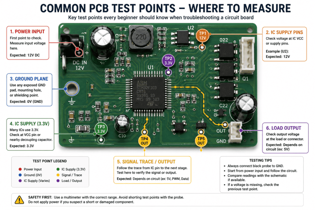
Step 3: Measure Voltage at Test Points
- Power the board on using a current-limited supply if possible for safety
- Set your multimeter to DC voltage mode on the 20V range
- Place the black probe on ground and touch the red probe to each test point or IC supply pin
- Compare each reading to the expected design voltage (commonly 3.3V or 5V rails)
Step 4: Test Individual Components (Resistors, Diodes, Transistors)
| Component | Multimeter Mode | Good Reading | Bad Reading |
|---|---|---|---|
| Resistor | Resistance (Ω) | Matches printed or schematic value within 5-10% | OL (open) or 0Ω (shorted) |
| Diode | Diode test mode | 0.5V to 0.8V forward, OL reverse | OL both ways (open) or 0V both ways (shorted) |
| Transistor junction | Diode test mode | Diode-like reading base to collector and base to emitter | Short or no response between junctions |
| Capacitor | Resistance (Ω) | Rising resistance toward infinity | Stuck at 0Ω or immediate OL |
| Fuse | Continuity | Beep | No beep — blown |
PCB Test Results Table
| Test | Healthy Result | Faulty Result |
|---|---|---|
| Trace continuity | Beep | No beep — broken trace |
| Power to ground short check | No beep (unpowered) | Beep — short circuit present |
| Test point voltage | Matches design spec | Missing, low, or unstable |
| Component test | Matches expected values | OL, 0Ω, or reading far outside spec |
💡 Tip: For a deeper dive into individual component testing including transistors and capacitors, see our How to Test a Diode with a Multimeter guide.
How to Test CCA (Cold Cranking Amps) with a Multimeter
What Is CCA and Why It Matters
Cold Cranking Amps (CCA) is a rating that measures how much current a battery can deliver for 30 seconds at 0°F (-18°C) while maintaining at least 7.2 volts. It directly indicates whether a battery has enough power to start an engine in cold weather.
Can a Standard Multimeter Measure CCA?
No. A standard multimeter cannot directly measure CCA. True CCA testing requires a dedicated battery load tester or a conductance tester that applies a calibrated load or high-frequency signal to the battery and calculates its cranking capability.
What a multimeter can do is give you an indirect indication of battery health through a basic voltage load test — useful as a rough estimate but not a substitute for a proper CCA test.
Step-by-Step Battery Load Test (CCA Estimate)
- Set your multimeter to DC voltage mode on the 20V range
- With the engine off, measure the resting battery voltage — a healthy 12V battery reads 12.6V or above
- Have a helper crank the engine while you watch the voltage
- Note the lowest voltage reached during cranking
CCA Results Table
| Cranking Voltage | What It Suggests |
|---|---|
| Stays above 9.6V during cranking | Battery is likely delivering adequate current |
| Drops to 9.0V to 9.6V | Battery is weak — have it professionally load tested |
| Drops below 9.0V | Battery is likely failing to meet its CCA rating |
⚠️ Important: This voltage drop test is only a rough indicator. For an accurate CCA measurement in amps, take the battery to an auto parts store or use a dedicated CCA/conductance tester. See our How to Test a Car Battery with a Multimeter guide for the complete voltage testing procedure.
Common Mistakes When Testing Motherboards, ECUs, and PCBs
Testing Resistance on a Powered Board
This is the single most common mistake. The multimeter sends its own small current for resistance and continuity tests — an energized board interferes with that current and can instantly blow the meter’s internal fuse. Always power down and disconnect before switching to resistance or continuity mode.
Skipping ESD Protection
Static discharge from your hand can destroy a sensitive chip even if the board looks completely fine afterward — and the damage may not show up until much later. Always ground yourself before handling any board.
Misreading In-Circuit Component Values
A component still soldered into a circuit is affected by every other component connected in parallel around it. A resistor may read lower than its actual value simply because current has another path to flow through. When a reading looks suspicious, lift one leg of the component to isolate it for an accurate out-of-circuit reading.
Ignoring Visual Inspection First
A ten second visual check for burn marks, bulging capacitors, or cracked solder joints often finds the fault faster than any electrical test. Always inspect the board visually before reaching for your multimeter.
FAQ
How do I know if my motherboard is fried?
Common signs include the system failing to power on at all, fans spinning briefly then stopping (a “one-second start”), a burning smell, visible scorch marks on the board, or repeated random crashes with no other explanation. Test the ATX voltage rails and check for short circuits with your multimeter to confirm. If the power supply voltages test correctly but the board still shows no signs of life, the motherboard itself has likely failed.
Can I test an ECU with a regular multimeter?
Yes, for basic checks. A standard multimeter can confirm the ECU is receiving power and a good ground connection, and can check the resting voltage on CAN bus wires. However, a multimeter cannot decode communication data or diagnose internal software faults. For deeper diagnostics beyond basic wiring checks, a dedicated OBD-II scan tool or oscilloscope is needed.
What voltage should the CMOS battery read?
A healthy CMOS battery (typically a CR2032 coin cell) should read 3.0V or above on a multimeter set to DC voltage mode. A reading below 2.8V means the battery is dead and needs replacing, which often resolves issues like the BIOS resetting, the system clock losing time, or boot failures.
How do I check for a short circuit on a PCB?
Power off and completely disconnect the board first. Set your multimeter to continuity mode. Touch one probe to the ground plane or a known ground point and the other probe to the power rail or suspected component. A continuous beep or a reading near 0Ω indicates a short circuit at that point. Narrow down the location by testing smaller sections of the circuit one at a time.
Can a multimeter measure CCA directly?
No. Cold Cranking Amps requires a dedicated battery load tester or conductance tester that applies a calibrated load to the battery. A multimeter can only perform an indirect voltage drop test during cranking, which gives a rough indication of battery health but not an actual CCA number in amps.
What does OL mean when testing a motherboard component?
OL means open loop — the resistance or continuity being measured is beyond what the multimeter can detect, indicating a broken internal connection. On a resistor, OL means it is open circuit and needs replacing. On a diode, OL in both directions (forward and reverse) also means the diode has failed open. OL is always a bad result for a component that should show a measurable value.
Conclusion
Testing a motherboard, ECU, BCM, TCM, or general PCB with a multimeter follows the same core principles every time: check power delivery first, check ground continuity second, look for short circuits third, and test individual components last.
For motherboards, always start with the CMOS battery and ATX voltage rails since these cause the majority of “dead computer” symptoms. For automotive modules, confirm power, ground, and CAN bus resting voltage before assuming the module itself has failed. For general PCBs, trace continuity and power-to-ground short checks catch most common faults quickly.
Remember that a multimeter cannot do everything; it cannot measure true CCA, decode CAN bus data, or measure capacitor ESR. Know these limits and use a dedicated tool when the job calls for it.
1 thought on “How to Test a Motherboard, ECU, and PCB with a Multimeter”