Your circuit is not working. The wiring looks correct. The power supply is fine. But something inside has failed.
Nine times out of ten it is a small component — a diode, a resistor, or a transistor. And the fastest way to find the faulty one is your multimeter.
In this guide you will learn how to test a diode with a multimeter using three different methods. You will also learn how to test resistors, LEDs, and transistors — all with the same tool.
What Is a Diode and Why Test It?
A diode is a small semiconductor component that allows electrical current to flow in one direction only. Think of it like a one-way valve for electricity. Current flows through freely in one direction and is blocked completely in the other.
Diodes are found in almost every electronic device — power supplies, car electronics, circuit boards, chargers, and LED lights.
What Does a Diode Do?
A diode converts AC voltage to DC voltage in power supplies. It protects circuits from reverse voltage. It regulates voltage in Zener diode applications. It emits light in LED applications.
When a diode fails, the circuit loses one of these functions, and the device stops working.
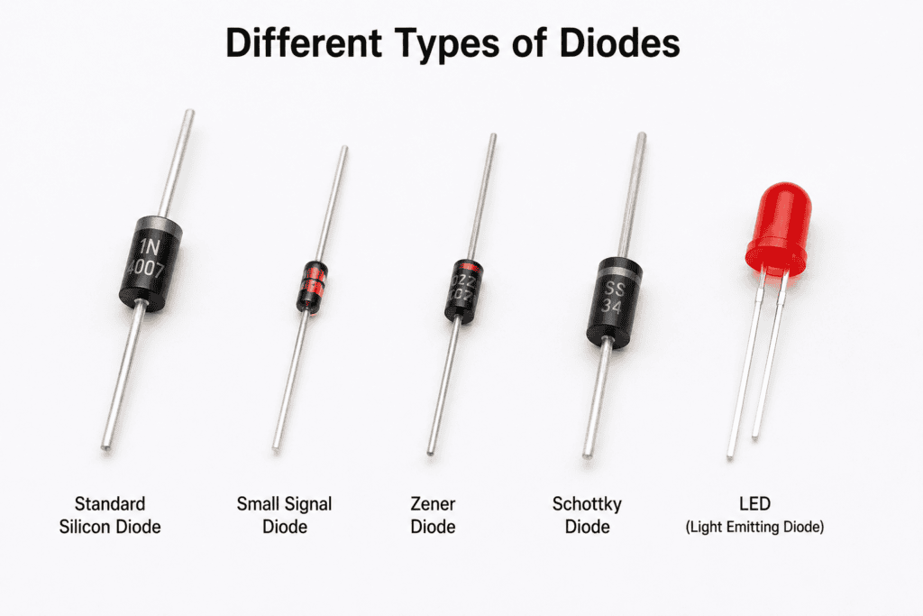
Types of Diodes You Will Come Across
Silicon diode: The most common type. Used in general-purpose rectification and protection. Forward voltage drop of 0.5V to 0.8V.
Germanium diode: Older type with a lower forward voltage drop of 0.2V to 0.3V. Found in vintage electronics.
Zener diode: Designed to work in reverse bias for voltage regulation.
Schottky diode: Very low forward voltage drop and fast switching. Common in high-frequency circuits.
LED (Light Emitting Diode): Emits light when forward-biased. Found in indicator lights and displays.
Signs of a Bad Diode
Look for these signs before picking up your multimeter:
- The device stops working completely
- A component gets unusually hot during operation
- Burn marks or physical damage on the diode body
- The circuit works sometimes but not consistently
- A power supply outputs incorrect voltage
What Is the Diode Test Mode on a Multimeter?
Diode test mode is a dedicated setting on a digital multimeter that applies a small voltage across a diode and measures the resulting voltage drop. This tells you directly whether the diode is working correctly.
Diode test mode is almost always the best method for testing diodes. It gives you a voltage drop reading that you can compare against known-good values.
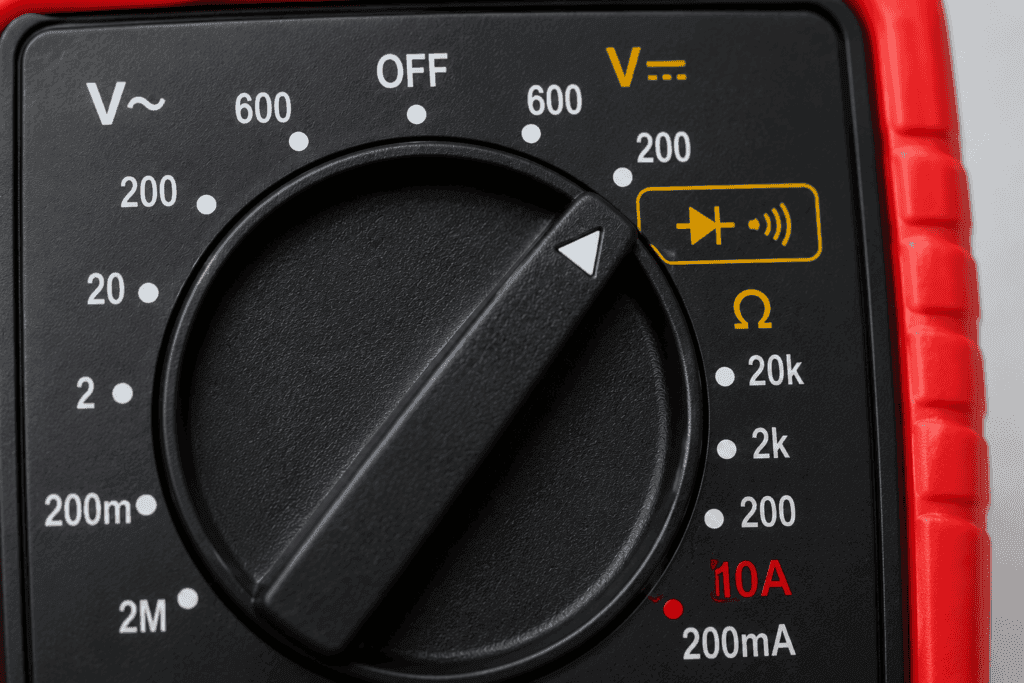
What Does the Diode Symbol Look Like on a Multimeter?
The diode test symbol looks like a triangle pointing toward a vertical line. It looks like an arrow blocked by a wall. Look for: →|
On most multimeters, the diode symbol shares a position on the dial with the continuity symbol. You switch between them using the function button.
Diode Test Mode vs Resistance Mode: Which Should You Use?
Always use diode test mode first. It is more reliable and provides a clear voltage-drop reading.
Use resistance mode only if your multimeter does not have a dedicated diode test mode.
Never use resistance mode on a diode that is still connected in a circuit. Other components create parallel paths that give false results.
How to Test a Diode with a Multimeter
What You Need
- A digital multimeter with diode test mode
- Red and black test leads
- The diode you want to test (removed from the circuit if possible)
Step 1: Turn Off Power and Discharge the Circuit
Turn off all power to the circuit. If the circuit contains capacitors, discharge them before testing. A charged capacitor gives false diode readings and can shock you.
Remove the diode from the circuit if possible. If not, disconnect at least one end from the circuit.
Step 2: Set the Multimeter to Diode Test Mode
Turn the dial to the diode test symbol (→|). On some multimeters, press the function button to switch from continuity mode to diode test mode.
Plug the black probe into the COM port. Plug the red probe into the VΩ port.
Step 3: Identify the Anode and Cathode
Before connecting the probes, you need to identify which end of the diode is which.
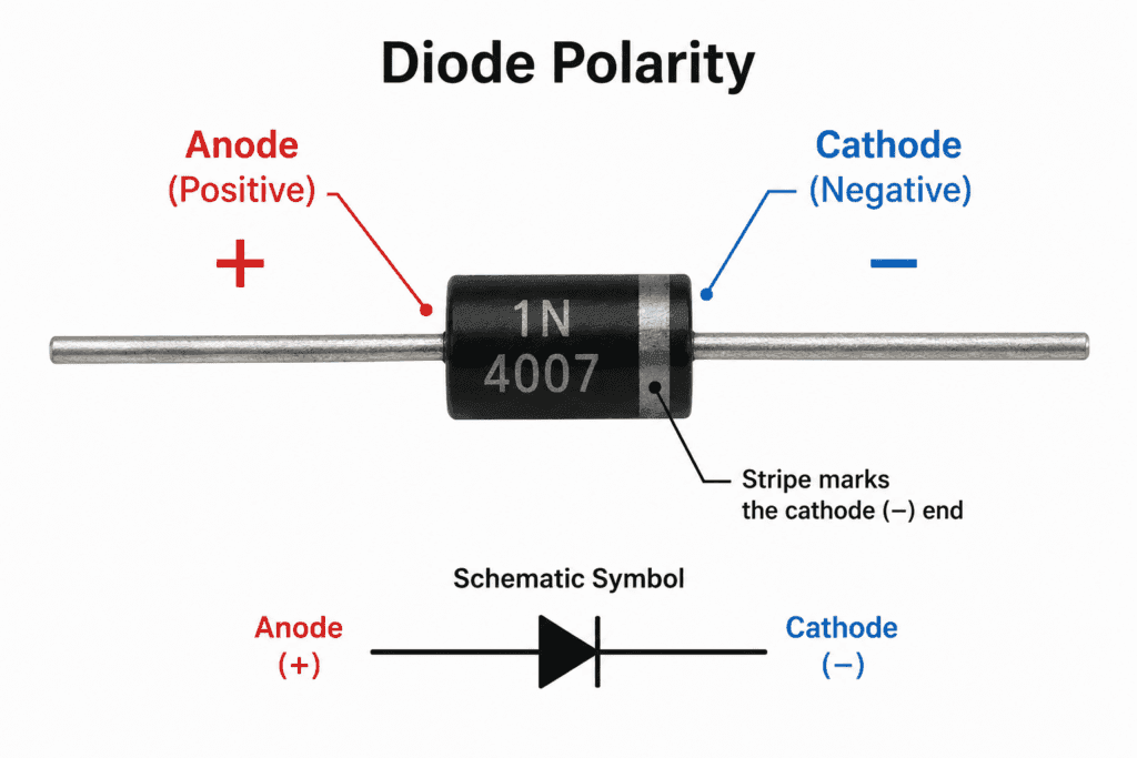
Anode: The positive end. No stripe marking. Cathode: The negative end. Marked with a silver or black stripe on the diode body.
Current flows from anode to cathode in normal operation.
Step 4: Connect the Probes (Forward Bias Test)
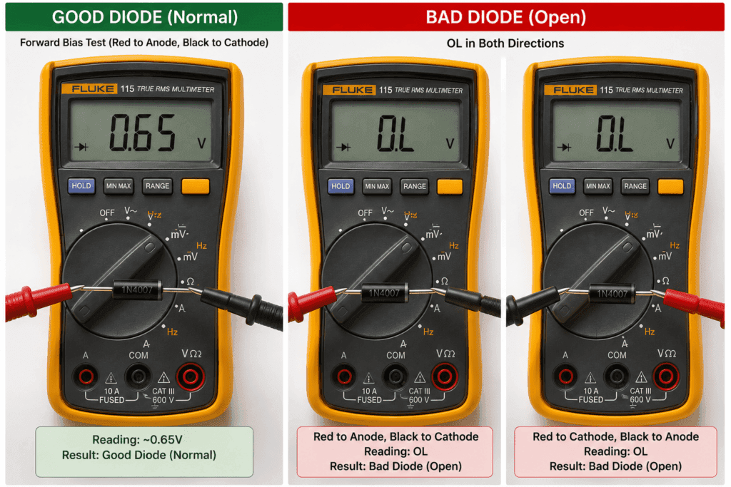
Touch the red probe to the anode (positive end, no stripe). Touch the black probe to the cathode (negative end, stripe side).
This is the forward bias test. You are checking if current flows normally through the diode in the correct direction.
Step 5: Reverse the Probes (Reverse Bias Test)
Now swap the probes. Touch the red probe to the cathode (stripe side) and the black probe to the anode (no stripe side).
This is the reverse bias test. You are checking that the diode blocks current correctly in the opposite direction.
Step 6: Read and Record Both Results
Write down the reading from each test and compare both to the results table below.
How to Read Diode Test Results
Good Diode Reading
A good silicon diode in forward bias reads between 0.5V and 0.8V. A good germanium diode in forward bias reads between 0.2V and 0.3V. In reverse bias, a good diode of any type displays OL.
Bad Diode Readings
Open-circuit diode: Reads OL in both directions. The diode is broken internally. No current flows in either direction. Replace it.
Shorted diode: Reads approximately the same low voltage in both directions (around 0.4V). The diode junction has failed. Current flows in both directions. Replace it.
Complete Diode Results Table
| Test | Good Diode | Open Diode (Bad) | Shorted Diode (Bad) |
|---|---|---|---|
| Forward bias | 0.5V to 0.8V | OL | 0.4V or similar |
| Reverse bias | OL | OL | 0.4V or similar |
| Replace? | No | Yes | Ye |
How to Test a Diode Using Resistance Mode
When to Use Resistance Mode Instead
Use resistance mode only when your multimeter does not have a dedicated diode test mode. It is less reliable but still gives useful information about whether a diode is working.
Step-by-Step Resistance Mode Diode Test
- Remove the diode from the circuit completely
- Set the multimeter to resistance mode (Ω)
- Touch the red probe to the anode and the black probe to the cathode
- Record the reading
- Reverse the probes and record the second reading
Resistance Mode Results Table
| Test Direction | Good Diode | Bad Diode |
|---|---|---|
| Forward bias (red to anode) | 1,000Ω to 10MΩ | OL or very low reading |
| Reverse bias (red to cathode) | OL | Same reading as forward |
⚠️ Important: Never use resistance mode on a diode that is still connected in a circuit. Other components create parallel paths and give you false results.
How to Test a Diode Using Continuity Mode
When to Use Continuity Mode
Continuity mode gives you a quick pass or fail check on a diode. It does not give you a voltage drop reading but tells you if the diode is open or shorted in seconds.
Step-by-Step Continuity Mode Diode Test
- Set the multimeter to continuity mode (sound wave symbol)
- Touch the red probe to the anode and the black probe to the cathode
- Listen for the result
- Reverse the probes and listen again
What the Beep Means for a Diode
| Test | Result | What It Means |
|---|---|---|
| Forward bias | Short beep or tone | Diode is conducting — good sign |
| Reverse bias | No beep — OL | Diode is blocking — good sign |
| Both directions beep | Shorted diode | Replace it |
| Neither direction beeps | Open diode | Replace it |
💡 Tip: Continuity mode is useful for a fast check but always follow up with diode test mode for a confirmed result.
How to Test an LED with a Multimeter
What Is an LED?
An LED (Light Emitting Diode) is a type of diode that emits light when forward-biased. Testing an LED is almost identical to testing a standard diode. The key difference is that a good LED may actually glow faintly during the forward bias test.
Step-by-Step LED Test
- Set your multimeter to diode test mode
- Touch the red probe to the longer leg of the LED (anode — positive)
- Touch the black probe to the shorter leg (cathode — negative)
- Observe the reading and the LED
LED Test Results
| Result | What It Means |
|---|---|
| 1.8V to 3.5V and LED glows faintly | LED is good |
| OL in forward bias | LED is open; replace it |
| Low reading in both directions | LED is shorted; replace it |
| No glow but reading is normal | May be an infrared LED not visible |
💡 Tip: LEDs have a higher forward voltage drop than standard silicon diodes. A reading of 1.8V to 3.5V is completely normal for an LED.
How to Test a Resistor with a Multimeter
What Is a Resistor?
A resistor is a passive component that limits or controls the flow of current in a circuit. It is measured in ohms (Ω). Resistors rarely fail, but when they do, they either go open circuit or drift far from their rated value.
Step-by-Step Resistor Test
- Turn off all power to the circuit
- Remove the resistor or disconnect at least one leg from the circuit
- Set the multimeter to resistance mode (Ω)
- Touch one probe to each end of the resistor — polarity does not matter
- Read the value on the display
How to Read Resistor Values on a Multimeter
The display shows the resistance in ohms (Ω), kilohms (kΩ), or megohms (MΩ).
Ω = ohms. kΩ = kilohms (1,000 ohms). MΩ = megohms (1,000,000 ohms).
Resistor Test Results Table
| Reading | What It Means |
|---|---|
| Within 5 to 10% of rated value | Resistor is good |
| More than 20% above rated value | Resistor has drifted — replace it |
| OL | Resistor is open circuit — replace it |
| 0Ω or near zero | Resistor is shorted — replace it |
Example: A 1kΩ resistor should read between 950Ω and 1050Ω. A reading of 1500Ω or OL means replace it.
💡 Tip: Always remove at least one leg of a resistor from the circuit before testing. Other components create parallel resistance paths that give false readings.
How to Test a Transistor with a Multimeter (HFE)
What Is a Transistor?
A transistor is a semiconductor component that amplifies or switches electronic signals. It has three terminals: the base, the collector, and the emitter.
Transistors come in two main types. NPN transistors: current flows from the collector to the emitter when the base receives a positive signal. PNP transistors: current flows from the emitter to the collector when the base receives a negative signal.
What Does HFE Mean on a Multimeter?
HFE is the DC current gain of a transistor. It tells you how much the transistor amplifies the base current into the collector current.
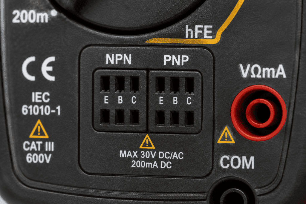
Most multimeters have a dedicated HFE socket — a set of small holes labeled E, B, and C (emitter, base, collector) for both NPN and PNP transistors. You insert the transistor legs into the correct holes, and the multimeter displays the HFE value.
Step-by-Step Transistor Test Using HFE Mode
- Set the multimeter dial to the HFE position
- Identify whether your transistor is NPN or PNP — check the component datasheet
- Insert the transistor legs into the correct NPN or PNP slots — match E to emitter, B to base, C to collector
- Read the HFE value on the display
- Compare the reading to the transistor datasheet specification
A healthy transistor reads an HFE value within the range in its datasheet. A reading of 0 or OL means the transistor has failed.
How to Test a Transistor Using Diode Mode
You can also test a transistor using diode test mode by testing each junction individually. A transistor has two junctions — base to collector and base to emitter — both behave like diodes.
- Set the multimeter to diode test mode
- Test base to collector: red probe on base, black probe on collector — should read 0.5V to 0.7V for NPN
- Test base to emitter: red probe on base, black probe on emitter — should read 0.5V to 0.7V for NPN
- Reverse both tests — both should read OL
- Test collector to emitter in both directions — should read OL both ways
Transistor Test Results
| Test | Good NPN Transistor | Bad Transistor |
|---|---|---|
| Base to collector (forward) | 0.5V to 0.7V | OL or near 0V |
| Base to emitter (forward) | 0.5V to 0.7V | OL or near 0V |
| Reverse of both tests | OL | Any reading |
| Collector to emitter | OL both ways | Any reading |
| HFE reading | Within datasheet range | 0 or OL |
Common Mistakes When Testing Diodes and Components
Testing a Live Circuit
Never test diodes, resistors, or transistors with power still connected. The voltage from the circuit interferes with your reading and gives completely false results. Always turn off power first.
Getting Anode and Cathode Backwards
If you connect the red probe to the cathode and black probe to the anode during the forward bias test, you get OL — the same result as a bad diode. Always check the stripe on the diode body to identify the cathode before connecting.
Using Resistance Mode on a Connected Component
Resistance mode on a component still connected in circuit gives false readings. Other components create parallel paths that lower the measured resistance. Disconnect at least one leg before testing.
Not Discharging Capacitors Before Testing
Charged capacitors push voltage through the diode during testing. This gives false readings and can also shock you. Always discharge capacitors before any component testing.
FAQ
What is a good diode reading on a multimeter?
A good silicon diode in forward bias reads between 0.5V and 0.8V on diode test mode. In reverse bias, it displays OL. A germanium diode reads between 0.2V and 0.3V in forward bias. If the diode reads OL in both directions, it is open and needs replacing. If it reads the same low voltage in both directions, it is shorted and needs replacing.
What does OL mean when testing a diode?
OL means open-loop — no current is flowing through the diode in that direction. In reverse bias, this is normal and means the diode is blocking current correctly. In forward bias, OL means the diode is open-circuit and has failed internally. Replace it.
Can I test a diode without removing it from the circuit?
You can try, but results may not be accurate. Other components connected in parallel with the diode affect the reading. For the most reliable result, remove at least one end of the diode from the circuit before testing.
What is HFE on a multimeter?
HFE is the DC gain of a transistor. It measures how much the transistor amplifies current. Most multimeters have a small socket labeled HFE with slots for NPN and PNP transistors. Insert the transistor into the correct slot, and the multimeter displays the gain value. Compare this to the transistor datasheet to confirm it is working correctly.
How do I test an LED with a multimeter?
Set the multimeter to diode test mode. Touch the red probe to the longer leg (anode) and the black probe to the shorter leg (cathode). A good LED reads between 1.8V and 3.5V and may glow faintly during the test. OL in forward bias means the LED is open and needs replacing.
What should a resistor read on a multimeter?
A resistor should read within 5 to 10% of its rated value. A 1kΩ resistor should read between 950Ω and 1050Ω. An OL reading means the resistor is open circuit. A reading close to zero means it is shorted. Both mean the resistor needs replacing.
Conclusion
Testing diodes, resistors, LEDs, and transistors with a multimeter is a skill that saves you hours of troubleshooting.
For diodes, always start with diode test mode. A good silicon diode reads 0.5V to 0.8V in forward bias and OL in reverse bias. Anything else means the diode has failed.
For resistors, use resistance mode and compare the reading to the rated value on the component body. For transistors, use HFE mode for a quick gain check or diode mode to test each junction individually.
Always turn off power before testing. Always discharge capacitors. And always disconnect at least one leg of the component from the circuit for an accurate reading.