Your PC will not turn on. Or it turns on and randomly shuts off. Or you smell something burning near the case.
Before replacing expensive components like the motherboard or GPU, test the power supply first. A failing PSU is one of the most common causes of these symptoms, and it is also one of the easiest components to test yourself.
In this guide, you will learn three methods to test a PSU with a multimeter, how to test a laptop charger, and how to test a rectifier. Every section includes step-by-step instructions and a complete voltage results table.
What Is a PSU and Why Test It?
What Does a PSU Do?
A power supply unit (PSU) converts AC power from your wall outlet into the DC voltages your computer components need to operate. It supplies three main voltage rails — 3.3V, 5V, and 12V — through a series of connectors to the motherboard, CPU, GPU, storage drives, and cooling fans.
Without stable voltage from the PSU, every other component in your PC suffers. Even a partially failing PSU that still powers on can cause random crashes, data corruption, and damage to expensive components over time.
Signs of a Bad Power Supply
Look for these signs before testing. Any one of them suggests the PSU may be failing:
- PC will not turn on at all
- PC turns on briefly then shuts off immediately
- Random restarts or shutdowns during normal use
- System crashes during demanding tasks like gaming or video editing
- Burning smell or scorch marks near the PSU or rear of the PC case
- PSU fan making grinding or buzzing sounds instead of a low hum
- GPU or CPU errors that cannot be explained by driver or software issues
⚠️ Important: If you smell burning coming from your PC unplug it from the wall immediately. A failing PSU can cause a fire.
When Should You Test Your PSU?
Test your PSU when you experience any of the symptoms above and you have already ruled out other common causes such as loose cable connections, tripped circuit breakers, and software or driver issues.
Also test a used or second-hand PSU before installing it in a build. And test a PSU from an old PC before reusing it in a new build.
Safety Warning: Read Before You Start
⚠️ Critical Safety Warning: Never open the PSU casing for any reason. The internal capacitors store lethal voltage even after the PSU is unplugged. There is no user-serviceable component inside a PSU. If the PSU fails testing it must be replaced — not repaired.
Additional safety rules to follow throughout this guide:
- Always unplug the PSU from the wall before connecting or disconnecting cables
- Do not touch any pins other than the ones specified in each test
- Do not let multimeter probes touch each other while connected to a live PSU
- Keep the PSU on a non-conductive surface during testing
- Never bypass or remove internal fuses
What You Need Before Testing
- A digital multimeter with a DC voltage setting
- A metal paper clip or a PSU jumper tool
- The PSU you want to test (disconnected from all PC components except the 24-pin ATX cable)
- Insulated rubber gloves recommended
How to Set Up Your Multimeter for PSU Testing
- Plug the black probe into the COM port
- Plug the red probe into the VΩ port
- Turn the dial to DC voltage mode — look for V— or VDC on the dial
- Select the 20V range if your multimeter is not auto-ranging
- Touch both probes together to confirm the meter reads close to 0V
What PSU Voltages Should You Expect?
ATX Voltage Rails Explained
A standard ATX PSU supplies several voltage rails through the 24-pin connector and other connectors. Each rail powers specific components:
3.3V rail: Powers the motherboard chipset, RAM, and some storage devices. 5V rail: Powers USB ports, storage drives, and some older components. 12V rail: Powers the CPU, GPU, case fans, and storage drives. The most critical rail in modern systems. 5VSB (5V Standby): Keeps the motherboard in standby mode when the PC is off. Powers on with the PSU plugged in even before the PC turns on.
PSU Voltage Rail Results Table
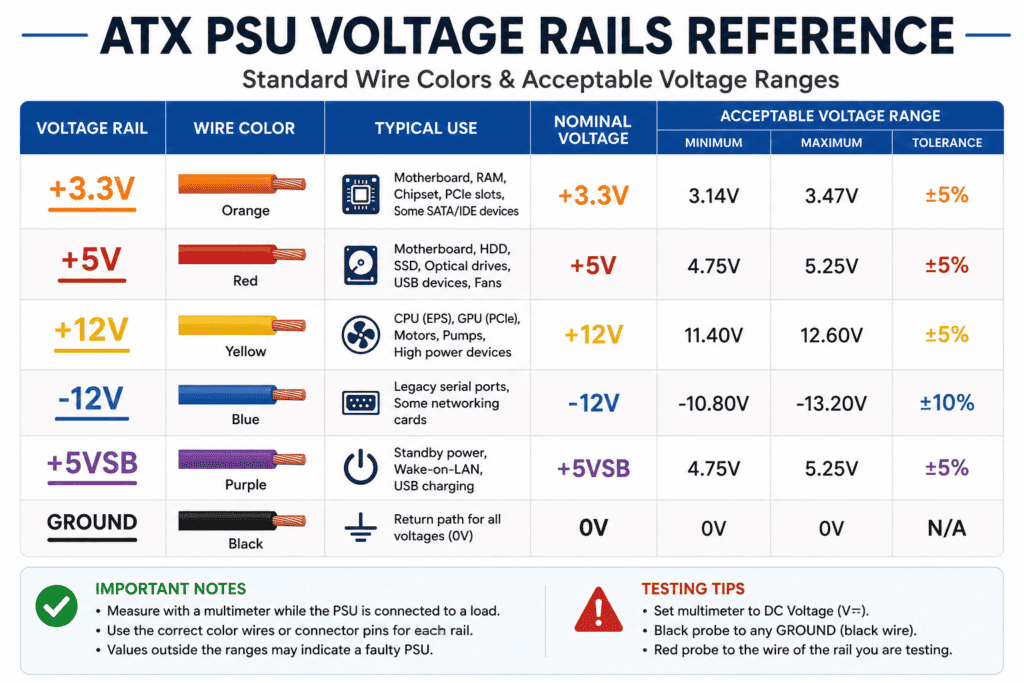
| Voltage Rail | Wire Color | Nominal Voltage | Acceptable Range (5% tolerance) | Bad Reading |
|---|---|---|---|---|
| 3.3V | Orange | 3.3V | 3.14V to 3.47V | Below 3.14V or above 3.47V |
| 5V | Red | 5V | 4.75V to 5.25V | Below 4.75V or above 5.25V |
| 12V | Yellow | 12V | 11.4V to 12.6V | Below 11.4V or above 12.6V |
| 5VSB | Purple | 5V | 4.75V to 5.25V | Below 4.75V or above 5.25V |
| Ground | Black | 0V | 0V | Any reading above 0.1V |
What Is the 5% Tolerance Rule?
The ATX specification allows each voltage rail to vary by up to 5% above or below its nominal value. A 12V rail reading 11.8V is fine. A 12V rail reading 11.0V is outside the tolerance and indicates a failing PSU.
If any rail reads outside its 5% tolerance range under normal conditions, the PSU should be replaced.
Method 1: Paperclip Test (Quick Power On Check)
What the Paperclip Test Tells You
The paperclip test tells you one thing: whether the PSU can power on. If the PSU fan spins after the paperclip test the PSU is at least partially functional.
What the Paperclip Test Cannot Tell You
The paperclip test cannot tell you whether the voltage rails are within tolerance. A PSU can pass the paperclip test and still deliver incorrect voltages that damage your components. Always follow the paperclip test with a multimeter voltage test.
How to Identify the Green and Black Pins
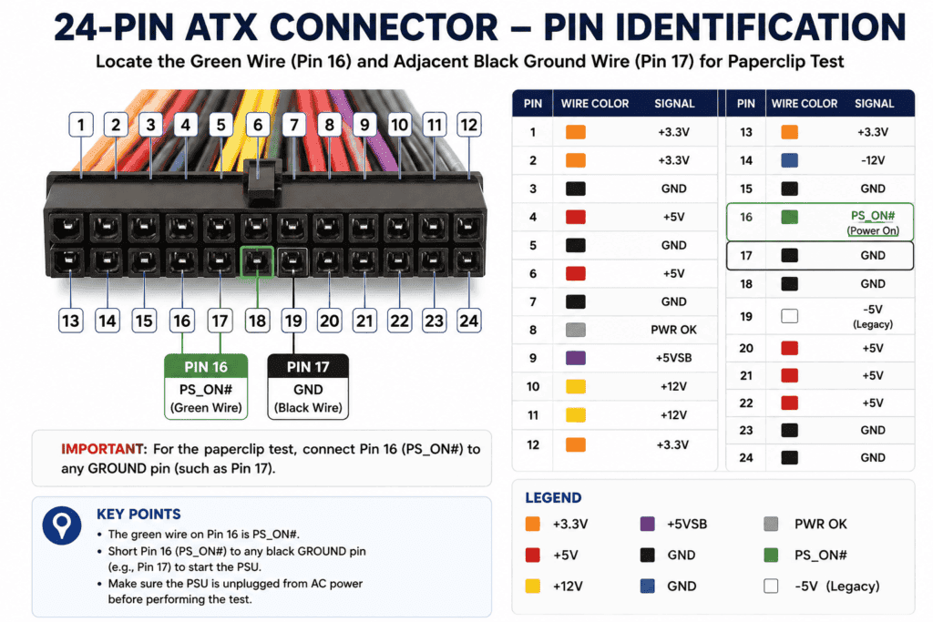
On the 24-pin ATX connector hold the connector with the clip side facing up and the pins facing toward you. Count from left to right:
- Pin 16 is the green wire — this is the power-on signal (PS-ON)
- Pin 17 is the adjacent black wire — this is a ground pin
These are the only two pins you use for the paperclip test.
Step-by-Step Paperclip Test
- Turn off the PSU using its rear power switch
- Unplug the PSU from the wall outlet
- Disconnect all cables from the PSU except the main AC power cable and the 24-pin ATX cable
- Locate Pin 16 (green wire) and Pin 17 (black ground wire) on the 24-pin connector
- Bend a metal paper clip into a U-shape
- Insert one end of the paper clip into Pin 16 (green) and the other end into Pin 17 (black)
- Make sure the paper clip does not touch any other pins
- Plug the PSU back into the wall outlet
- Turn on the PSU using its rear power switch
- Observe the PSU fan
Paperclip Test Results
| Result | What It Means |
|---|---|
| Fan spins and keeps spinning | PSU powers on — proceed to multimeter test |
| Fan spins briefly then stops | Normal for PSUs with zero-RPM mode — still proceed to multimeter test |
| Fan does not spin at all | PSU may be dead — check wall outlet first, then consider replacement |
💡 Tip: Many modern PSUs have a zero-RPM fan mode where the fan only spins briefly and then stops at low loads. This is normal behavior and does not mean the PSU has failed.
Method 2: How to Test a PSU with a Multimeter
Keep the paper clip connected from the previous test. The PSU must be powered on for voltage measurements.
Step 1: Set Up the Multimeter for DC Voltage
Set your multimeter dial to DC voltage mode (V— or VDC). Select the 20V range if your multimeter is not auto-ranging. Plug the black probe into COM and the red probe into VΩ.
Step 2: Keep the Paperclip Connected
The PSU must be powered on during voltage testing. Leave the paper clip in Pin 16 and Pin 17. Turn on the PSU using the rear power switch.
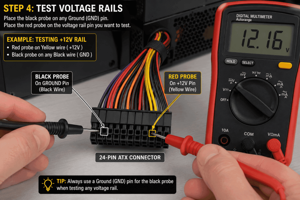
Step 3: Connect the Black Probe to Ground
Touch the black probe to any black wire pin on the 24-pin connector. This is your ground reference. Keep the black probe here throughout all voltage measurements.
Step 4: Test Each Voltage Rail
With the black probe held firmly on a ground pin, touch the red probe to each voltage pin individually:
- Orange wire pins for 3.3V readings
- Red wire pins for 5V readings
- Yellow wire pins for 12V readings
- Purple wire pin for 5VSB reading
Step 5: Read and Record the Results
Read and write down the voltage displayed for each pin. Compare every reading to the PSU voltage rail results table above.
PSU Multimeter Voltage Results Table
| Rail | Wire Color | Your Reading | Good? |
|---|---|---|---|
| 3.3V | Orange | _____ | 3.14V to 3.47V = Yes |
| 5V | Red | _____ | 4.75V to 5.25V = Yes |
| 12V | Yellow | _____ | 11.4V to 12.6V = Yes |
| 5VSB | Purple | _____ | 4.75V to 5.25V = Yes |
If any reading falls outside the acceptable range, the PSU is failing and should be replaced.
Reading PSU Voltage Rails
What Is the 3.3V Rail?
The 3.3V rail powers the motherboard chipset, RAM modules, and some PCIe devices. A low 3.3V reading causes system instability, random crashes, and RAM errors that are often misdiagnosed as faulty memory.
What Is the 5V Rail?
The 5V rail powers USB ports, older storage devices, and some motherboard components. A low 5V reading causes USB device failures, storage corruption, and boot issues.
What Is the 12V Rail?
The 12V rail is the most critical rail in modern systems. It powers the CPU through the ATX12V connector, the GPU through PCIe power connectors, and all case fans and storage drives. A low or unstable 12V reading is the most common cause of GPU crashes, CPU instability, and random system shutdowns.
What Is the Power Good (PG) Signal?
The Power Good signal is a signal sent by the PSU to the motherboard confirming that all voltage rails are stable and within tolerance. The PSU sends this signal between 100ms and 500ms after powering on.
If the PG signal is delayed beyond 500ms or is 0ms the PC may fail to boot or experience instability. A PSU tester can measure the PG signal — a standard multimeter cannot.
Complete ATX Voltage Rail Table
| Rail | Nominal | Minimum | Maximum | Pin Wire Color |
|---|---|---|---|---|
| 3.3V | 3.3V | 3.14V | 3.47V | Orange |
| 5V | 5V | 4.75V | 5.25V | Red |
| 12V | 12V | 11.4V | 12.6V | Yellow |
| 5VSB | 5V | 4.75V | 5.25V | Purple |
| Ground | 0V | 0V | 0V | Black |
How to Test a Laptop Charger with a Multimeter
What Is a Laptop Charger?
A laptop charger converts AC power from the wall into DC voltage that charges the laptop battery and powers the laptop directly. Most laptop chargers output between 19V and 20V DC through a barrel connector or USB-C connector.
Signs of a Bad Laptop Charger
- Laptop does not charge when plugged in
- Laptop charges very slowly
- Charger gets unusually hot during normal use
- Laptop works on battery but shuts off when charger is connected
- Charging indicator light does not come on
Step-by-Step Laptop Charger Test
- Plug the charger into the wall outlet
- Do not connect it to the laptop yet
- Set your multimeter to DC voltage mode (V—)
- Select a range above the expected output voltage (usually 20V or auto-range)
- Insert the red probe into the center hole of the barrel connector (positive)
- Touch the black probe to the outside metal barrel of the connector (negative/ground)
- Read the voltage on the display
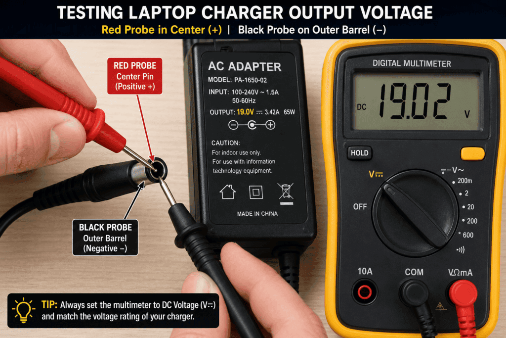
Laptop Charger Voltage Results Table
| Reading | What It Means | What to Do |
|---|---|---|
| Within 5% of rated output voltage | Charger is working correctly | No action needed |
| Below rated voltage by more than 5% | Charger is failing | Replace the charger |
| 0V | Charger has no output | Check wall outlet then replace charger |
| Significantly above rated voltage | Charger is over-volting | Replace; risk of battery damage immediately |
Example: A charger rated 19.5V should read between 18.5V and 20.5V. A reading of 16V or 0V means the charger needs replacing.
⚠️ Warning: For USB-C laptop chargers use a USB-C power meter instead of a standard multimeter. Testing USB-C connectors with standard probes can damage the connector pins.
How to Test a Rectifier with a Multimeter
What Is a Rectifier?
A rectifier converts AC voltage into DC voltage. It is found inside power supplies, battery chargers, alternators, and many electrical appliances. A rectifier is made up of diodes — usually four arranged in a bridge configuration. When a rectifier fails, it causes incorrect or fluctuating DC output, overheating, or complete power failure.
Signs of a Bad Rectifier
- Device outputs AC voltage instead of DC voltage
- Output voltage is much lower than rated
- Device overheats during normal operation
- Buzzing or humming sound from the device
- Blown fuse caused by a shorted rectifier diode
Step-by-Step Rectifier Test
- Turn off and unplug the device containing the rectifier
- Discharge any capacitors in the circuit before testing
- Locate the rectifier — it is usually a small square or rectangular component with 4 pins (AC input, AC input, DC positive, DC negative)
- Set your multimeter to diode test mode (→| symbol)
- Test each of the 4 diodes inside the rectifier by placing the red probe on the anode and black probe on the cathode of each diode
Rectifier Test Results Table
| Test | Good Reading | Bad Reading |
|---|---|---|
| Each diode forward bias | 0.5V to 0.8V | OL or near 0V |
| Each diode reverse bias | OL | Any voltage reading |
| Any diode reading same in both directions | Diode is shorted — rectifier failed | Replace rectifier |
| Any diode reading OL in both directions | Diode is open — rectifier failed | Replace rectifier |
💡 Tip: If any single diode in the rectifier fails the entire rectifier unit usually needs replacing. Individual diodes inside a bridge rectifier module are not user-replaceable in most cases.
Method 3: PSU Tester (Alternative Method)
What Is a PSU Tester?
A PSU tester is a dedicated tool that plugs directly into the 24-pin ATX connector and displays all voltage rail readings simultaneously on an LCD screen. It also measures the Power Good (PG) signal, which a standard multimeter cannot detect.
PSU Tester vs Multimeter: Which Should You Use?
| Feature | Multimeter | PSU Tester |
|---|---|---|
| Measures voltage rails | Yes — one at a time | Yes — all at once |
| Measures PG signal | No | Yes |
| Cost | Already own it | $15 to $50 extra |
| Accuracy | Very accurate | Accurate |
| Speed | Slower — one pin at a time | Fast — all rails at once |
| Best for | Detailed individual rail testing | Quick overall PSU health check |
For most home users, a multimeter is enough. If you regularly build or repair PCs a dedicated PSU tester is a worthwhile addition to your toolkit.
What to Do If Your PSU Fails the Test
Can a PSU Be Repaired?
No. PSUs are sealed units that are not designed for user repair. The internal components store dangerous voltages even after unplugging. Never attempt to open or repair a PSU. It must be replaced.
What to Look for When Buying a Replacement PSU
When selecting a new PSU, keep these factors in mind:
- Wattage: Calculate your system’s total power draw and choose a PSU with at least 20% headroom above that figure
- 80 Plus rating: Choose at least 80 Plus Bronze. Gold or higher is recommended for efficiency and longevity
- Brand reputation: Choose established brands with good warranty support
- Modular vs non-modular: Modular PSUs allow you to use only the cables you need — better for cable management
- Warranty: Quality PSUs come with 5 to 10 year warranties — shorter warranties often indicate lower quality components
FAQ
What voltage should a PSU read on a multimeter?
A healthy PSU should read within 5% of each nominal voltage. The 3.3V rail should read between 3.14V and 3.47V. The 5V rail should read between 4.75V and 5.25V. The 12V rail should read between 11.4V and 12.6V. Any reading outside these ranges indicates a failing PSU that needs replacing.
What is the paperclip test for a PSU?
The paperclip test is a quick method to check if a PSU can power on without a motherboard. You insert a bent paper clip into Pin 16 (green wire) and Pin 17 (adjacent black ground wire) of the 24-pin ATX connector. If the PSU fan spins, the unit can power on. The test does not check voltage accuracy — always follow it with a multimeter voltage test.
How do I test a laptop charger with a multimeter?
Plug the charger into the wall but do not connect it to the laptop. Set your multimeter to DC voltage mode. Insert the red probe into the center of the barrel connector and touch the black probe to the outer barrel. The reading should be within 5% of the rated output voltage printed on the charger label. A reading of 0V or significantly below rated voltage means the charger needs replacing.
What does a bad PSU reading look like?
A bad PSU reading is any voltage rail that falls outside its 5% tolerance. For example, the 12V rail reading 10.5V, the 5V rail reading 4.2V, or the 3.3V rail reading 2.9V all indicate a failing PSU. A reading of 0V on any active rail means that rail has failed.
Can I test a PSU without removing it from the PC?
Yes. You can perform the multimeter voltage test with the PSU still installed in the PC case. However, you need to use the paperclip method to power on the PSU with the motherboard disconnected, or test voltages while the PC is running by accessing the 24-pin connector. Testing with the PSU still installed is perfectly safe as long as you follow the safety rules in this guide.
What is the Power Good signal on a PSU?
The Power Good (PG) signal is a signal sent from the PSU to the motherboard confirming that all voltage rails are stable and ready. The PSU sends this signal between 100ms and 500ms after turning on. A PG signal outside this range causes boot failures or random instability. A standard multimeter cannot measure the PG signal — use a dedicated PSU tester to check it.
Conclusion
Testing a PSU with a multimeter is a straightforward two-step process. Run the paperclip test first to confirm the PSU can power on. Then use the multimeter to check every voltage rail against the 5% tolerance table.
A healthy PSU shows 3.3V between 3.14V and 3.47V, 5V between 4.75V and 5.25V, and 12V between 11.4V and 12.6V. Any reading outside these ranges means the PSU needs replacing.
For laptop chargers, test the DC output voltage at the barrel connector against the rated voltage on the label. For rectifiers, use diode test mode to test each diode junction individually.
Never open a PSU casing for any reason. If your PSU fails the test, replace it — do not attempt a repair.