A motor trips a breaker for no obvious reason. A cable that has been in the ground for years is due for inspection before a new installation goes live. A standard multimeter reads fine, but something still feels wrong with the wiring. In every one of these situations, the right tool is not a multimeter, it is an insulation resistance tester.
This guide covers what an insulation resistance tester actually is, how it fundamentally differs from a standard multimeter, how to use one safely, and how to interpret your readings correctly.
What Is an Insulation Resistance Tester?
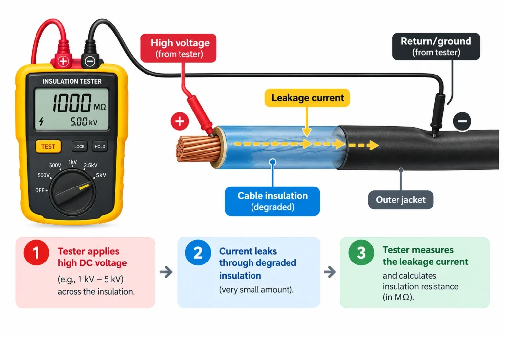
An insulation resistance tester is an instrument that measures the resistance of electrical insulation by applying a high DC test voltage and measuring the tiny leakage current that passes through it, revealing insulation breakdown or degradation that a standard multimeter cannot detect.
Why It’s Called a Megger
You will hear this tool called an insulation tester, an insulation resistance meter, or simply a megger. Megger is technically a registered trademark of the Megger Group, the company that pioneered this category of instrument, but the name has become so widely used that it now functions as a generic term for the entire product category, similar to how people say “Xerox” for photocopying regardless of the actual brand.
How It Works
The tester applies a selectable high DC voltage, commonly 250V, 500V, 1000V, or higher, across the insulation being tested. Insulation that is healthy allows almost no current to pass through it. As insulation ages, absorbs moisture, or degrades from heat and chemical exposure, a small leakage current begins to flow through it. The tester measures this leakage current and calculates resistance using Ohm’s Law, displaying the result directly in megohms (MΩ) or gigohms (GΩ).
Insulation Tester vs Multimeter: The Key Difference
This is the single most important distinction to understand before using either tool.
A standard multimeter’s resistance mode applies only a few volts to take a reading, which is fine for testing a resistor or a wire’s conductor, but nowhere near enough voltage to reveal a weakness in insulation. A cable can measure as effectively infinite resistance on a standard multimeter’s ohms setting while still failing dramatically the moment real operating voltage, or the higher stress voltage from an insulation tester, is applied across it.
| Feature | Standard Multimeter | Insulation Resistance Tester |
|---|---|---|
| Test voltage applied | A few volts | 250V to 5000V (selectable) |
| What it measures | Resistance of a component or wire conductor | Resistance of the insulation surrounding a conductor |
| Typical reading range | Ohms to kilohms | Megohms to gigohms |
| Can reveal insulation breakdown | No | Yes |
| Safe to use on the actual insulation layer | Not designed for this purpose | Purpose-built for this |
💡 For general resistance testing of components and wires, see our How to Measure Resistance with a Multimeter guide instead.
Types of Insulation Testers
Analog vs Digital Insulation Testers
Older insulation testers used a hand-crank generator to produce the test voltage, with results read off an analog needle scale. A digital insulation tester or digital megger tester generates the test voltage electronically from an internal battery and displays the result as a precise numeric readout, and this is now the standard choice for nearly all modern testing.
Handheld vs Benchtop Insulation Test Equipment
A handheld insulation tester is portable and battery-powered, suited to field work on motors, cables, and panels in the location where the equipment actually lives. Larger benchtop insulation resistance test equipment is used in laboratory and manufacturing settings where higher precision and repeat testing at scale matter more than portability.
Choosing the Right Test Voltage
| Equipment Rated Voltage | Typical Test Voltage |
|---|---|
| Below 50V | 250V |
| 50V to 500V (most standard equipment) | 500V |
| 500V to 1000V | 1000V |
| High voltage cables and industrial equipment | 2500V to 5000V |
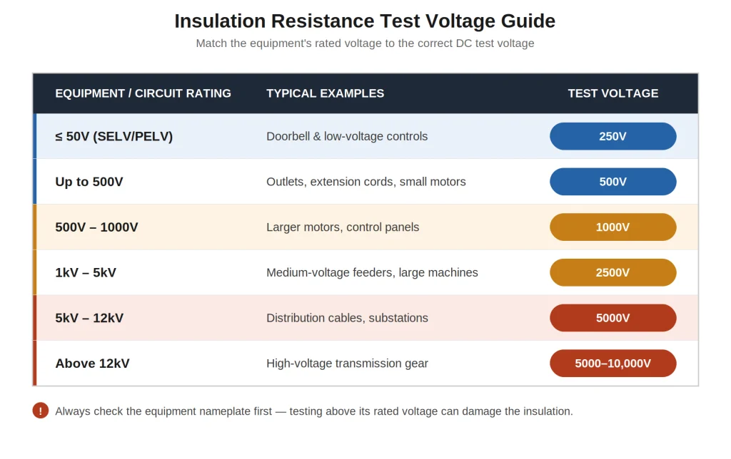
Always check the manufacturer’s specification for the specific equipment you are testing before selecting a test voltage, since applying too high a voltage can damage sensitive equipment.
How to Use an Insulation Resistance Tester: Step by Step
Step 1: De-Energize and Verify Zero Voltage
Completely disconnect power to the circuit or equipment. Use a standard voltage tester or multimeter first to confirm there is genuinely no voltage present before connecting the insulation tester.
Step 2: Discharge Any Stored Charge
Long cables and some equipment can hold a residual charge similar to a capacitor. Discharge this safely before connecting your test leads.
Step 3: Select the Correct Test Voltage
Choose the test voltage appropriate for the equipment’s rated voltage, using the table above as a starting reference.
Step 4: Connect the Test Leads
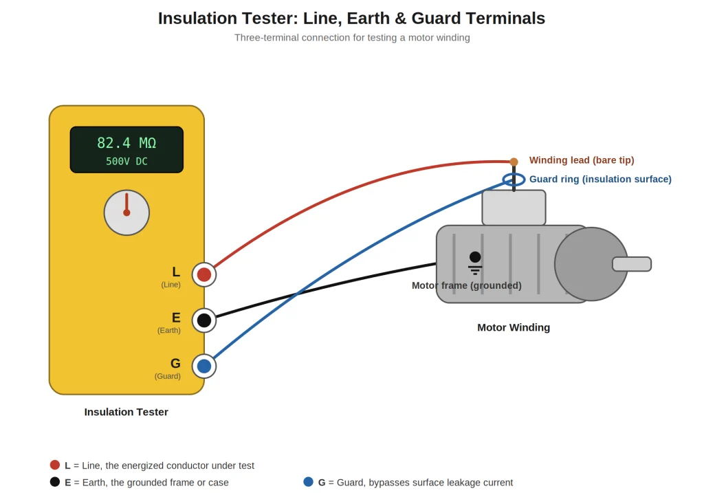
Connect the Line (L) lead to the conductor you are testing and the Earth (E) lead to ground or the equipment frame. Many insulation testers also include a Guard (G) terminal, used to eliminate surface leakage current from skewing your reading on dirty or damp equipment.
Step 5: Run the Test
Press and hold the test button, or activate the test, for the standard duration, commonly one minute, allowing the reading to stabilize.
Step 6: Read and Record the Result
Note the megohm reading displayed, along with the test voltage used and the temperature if possible, since insulation resistance readings are temperature-sensitive.
Step 7: Discharge the Equipment After Testing
The high test voltage charges the equipment similarly to a capacitor. Always allow the tester to safely discharge this charge, either automatically through the instrument or manually, before disconnecting your leads.
Safety Warnings
⚠️ Insulation testers apply genuinely dangerous voltage. Unlike a standard multimeter, the several hundred to several thousand volts DC these instruments generate can cause serious injury. Never touch the test leads or the equipment under test while a test is running.
- Always confirm the circuit is fully de-energized before connecting any leads
- Never use an insulation tester on live or energized circuits
- Always discharge the tested equipment after the test completes
- Keep bystanders clear of the test area during testing
- Use insulation test equipment rated for the environment you are working in
How to Interpret Insulation Resistance Readings
The General Rule of Thumb
A widely used general guideline states that acceptable insulation resistance should be at least 1 megohm per 1000 volts of operating voltage, plus 1 additional megohm. This is a starting reference point, not an absolute standard, always check equipment-specific manufacturer guidance or applicable industry standards for critical equipment.
Polarization Index (PI) for Motors and Generators
For larger motors and generators, technicians often compare the 10-minute reading to the 1-minute reading, called the Polarization Index. A ratio above roughly 2.0 generally indicates good, dry insulation, while a low ratio can suggest moisture or contamination even if the raw resistance value looks acceptable on its own.
Dielectric Absorption Ratio (DAR)
A faster alternative comparison uses the 60-second reading against the 30-second reading. Like the Polarization Index, this ratio helps reveal moisture or contamination trends that a single snapshot reading might miss.
Insulation Resistance Results Table
| Result Pattern | What It Suggests |
|---|---|
| High, stable megohm reading | Insulation is in good condition |
| Low megohm reading | Insulation has degraded, contaminated, or absorbed moisture |
| Reading climbs steadily during the test (good PI/DAR ratio) | Dry, healthy insulation |
| Reading stays flat or low throughout the test | Possible moisture or contamination |
| Reading trending downward over repeated tests on the same equipment over time | Insulation is degrading, worth monitoring closely |
Common Applications for Insulation Testing
- Testing motor windings before and after maintenance, including HVAC compressor motors
- Verifying cable insulation on new installations before energizing
- Preventive maintenance programs on transformers and switchgear
- Diagnosing nuisance breaker trips that a standard continuity or resistance test cannot explain
- Post-flood or post-moisture-exposure equipment assessment
💡 For HVAC-specific electrical diagnostics that complement insulation testing, see our Clamp Meter Guide for compressor and motor amperage checks.
How to Choose an Electrical Megger Tester
Key Features to Look For
- Multiple selectable test voltages (at minimum 250V, 500V, and 1000V)
- A Guard terminal to eliminate surface leakage interference
- Auto-discharge function for safety after testing
- A continuity or standard resistance mode built in for general use
- A reasonably wide megohm to gigohm display range
Megger Tester Price
Insulation resistance test equipment spans a wide price range depending on voltage capability and precision. Basic handheld digital insulation testers covering standard voltages sit at the more affordable end, while professional-grade units with higher test voltages and greater accuracy cost significantly more. As with any test equipment, prices change with the market, so check current listings from established brands before budgeting.
Common Mistakes When Using an Insulation Testers
Testing a live circuit. Always fully de-energize and verify zero voltage before connecting an insulation tester.
Selecting the wrong test voltage. Using a test voltage higher than the equipment is rated for can damage sensitive components.
Skipping the discharge step. Forgetting to discharge tested equipment after a high-voltage test leaves a genuine shock hazard behind.
Taking a single snapshot reading on large motors. For larger equipment, a Polarization Index or Dielectric Absorption Ratio comparison reveals problems a single quick reading misses entirely.
Ignoring surface contamination. Dirt, moisture, or dust on the equipment’s surface can create a false leakage path. Using the Guard terminal, when available, filters this out.
FAQ
What is an insulation resistance tester used for?
An insulation resistance tester, often called a megger, measures the condition of electrical insulation around wires, cables, and motor windings by applying a high DC test voltage and measuring the resulting leakage current. It is used to detect insulation degradation before it causes a short circuit, electrical fire, or equipment failure.
What is the difference between a megger and a multimeter?
A multimeter’s resistance mode applies only a few volts, enough to measure a component’s resistance but not enough to reveal weaknesses in electrical insulation. An insulation resistance tester applies a much higher voltage, typically 250V to 5000V, specifically designed to stress-test insulation and reveal breakdown that a standard multimeter’s low-voltage reading would completely miss.
What is a good insulation resistance reading?
A commonly cited general guideline suggests at least 1 megohm per 1000 volts of operating voltage plus 1 additional megohm as a minimum acceptable reading, though this varies by equipment type and applicable standards. For larger motors, a Polarization Index above roughly 2.0 is generally considered a sign of good, dry insulation.
How much does a megger tester cost?
Megger tester price varies significantly based on the voltage ranges and precision offered. Basic handheld digital insulation testers covering standard voltages are more affordable, while professional units with higher test voltages and greater accuracy cost more. Prices change over time, so check current listings from established manufacturers when budgeting.
Is it safe to use an insulation resistance tester?
Yes, when used correctly, but the voltages involved are genuinely dangerous, far higher than a standard multimeter produces. Always confirm the circuit is fully de-energized before testing, never touch the leads or equipment during a test, and always allow the equipment to discharge safely afterward.
Can I use an insulation tester on a live circuit?
No. Insulation resistance testers must only be used on completely de-energized equipment. Always verify zero voltage with a standard voltage tester or multimeter before connecting an insulation tester, since using it on a live circuit is extremely dangerous and can damage both the equipment and the tester.
Conclusion
An insulation resistance tester answers a question a standard multimeter cannot: is the insulation around this wire or winding actually still doing its job? By applying a genuinely higher test voltage and measuring the resulting leakage current, it reveals degradation long before a standard low-voltage resistance check would ever show a problem.
Always de-energize equipment fully before testing, select the correct test voltage for what you are working on, and remember to discharge the equipment afterward. For larger motors, comparing readings over time using the Polarization Index gives you a much clearer picture than any single snapshot reading alone.