
Your car is acting strange. A component stopped working. You replaced the fuse, but nothing changed.
The problem could be a bad relay. And how to test a relay with a multimeter is one of the most useful skills any car owner can learn. It takes less than five minutes and can save you hundreds of dollars in unnecessary repairs.
In this guide, you will learn how to test a relay with a multimeter step by step. You will also learn how to test an ignition coil, TPS sensor, fuel injectors, ECU, stator, and CAN bus wiring — all with your multimeter.
What Is a Relay and Why Do They Fail?
A relay is a small electrically operated switch. It uses a low-power signal to control a high-power circuit. You will find relays controlling fuel pumps, cooling fans, headlights, starter motors, and horns.
Relays fail for several reasons. Heat builds up over time and damages the internal contacts. Corrosion on the pins causes poor connections. Electrical overloads can burn out the internal coil. Most relays last the life of the vehicle, but some fail early — especially in hot or humid conditions.
Signs of a Bad Relay
Watch for these signs before reaching for your multimeter:
- A component stops working completely, such as the fan, fuel pump, horn, or headlights
- The engine cranks but will not start
- Clicking sound when you turn the ignition, but nothing happens
- A component works sometimes, but not always
- A burning smell is coming from the fuse box area
What You Need Before You Start
- A digital multimeter (any basic model works)
- The vehicle’s fuse box diagram
- A relay puller or flat screwdriver
- Jumper wires with alligator clips
- Your car battery or a 9V battery for bench testing
How to Test a Relay with a Multimeter
Testing a relay with a multimeter involves three separate tests. Each one checks a different part of the relay. All three tests together give you a complete picture of whether the relay is good or bad.
Step 1: Remove the Relay from the Fuse Box
Open your fuse box cover. Check the diagram on the inside of the lid to find the correct relay. Pull the relay straight out using a relay puller or your fingers. Most relays pop out easily.
⚠️ Warning: Turn off your ignition before removing any relay. This prevents accidental shorts.
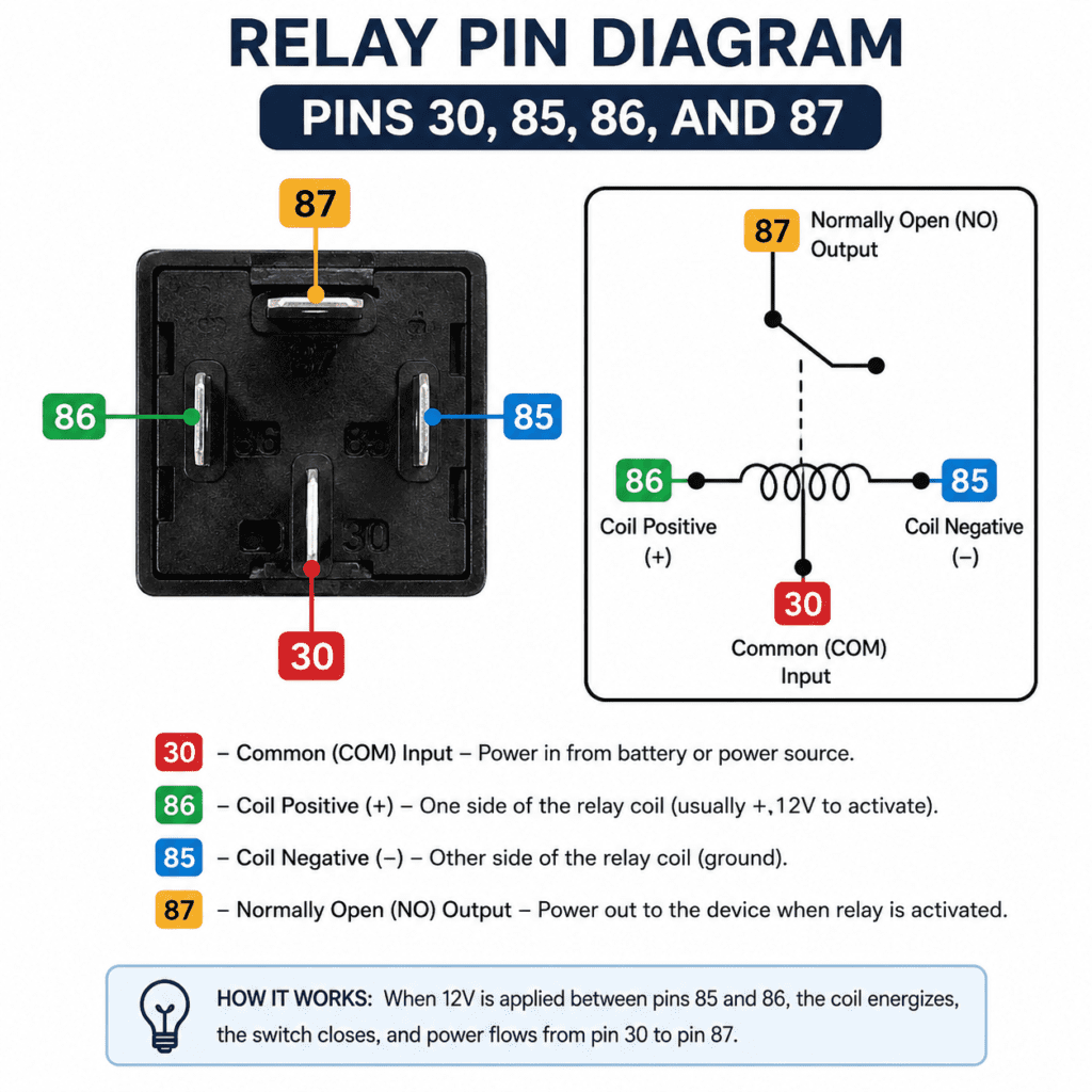
Step 2: Understand the Relay Pin Layout
Most automotive relays have 4 or 5 pins. Here is what each pin does:
| Pin Number | Function |
|---|---|
| 85 | Coil negative terminal |
| 86 | Coil positive terminal |
| 30 | Common contact — power input |
| 87 | Normally open contact — power output |
| 87a | Normally closed contact (5-pin relays only) |
Pins 85 and 86 control the electromagnetic coil. Pins 30 and 87 are the switch contacts that open and close when the coil is energized.
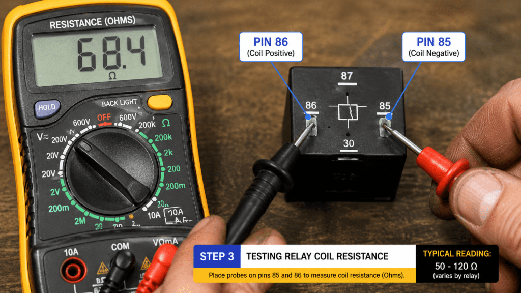
Step 3: Test the Coil Resistance
This test checks if the internal coil is intact.
- Set your multimeter to resistance mode (Ω)
- Touch the red probe to pin 86
- Touch the black probe to pin 85
- Read the result on the display
Step 4: Test Switch Pin Continuity
This test checks if the switch contacts are open at rest. They should be open when the relay is not energized.
- Keep your multimeter in resistance mode (Ω)
- Touch one probe to pin 30
- Touch the other probe to pin 87
- The reading should show OL (no continuity)
If the reading shows zero or near-zero ohms, the contacts are stuck closed. The relay is bad and needs replacing.
Step 5: Test the Energized Relay
This test confirms the relay switches on correctly when powered.
- Connect a jumper wire from your car battery’s positive terminal to pin 86
- Connect another jumper wire from the battery negative to pin 85
- You should hear a clear click when the coil energizes
- Set your multimeter to continuity mode
- Touch one probe to pin 30 and the other to pin 87
- You should hear a beep confirming continuity
💡 Tip: No click and no beep means the relay is bad. A click but no beep means the switch contacts have failed.
Step 6: Test the Voltage Output
- Keep the relay energized with your jumper wires
- Set your multimeter to DC voltage
- Touch the red probe to pin 87
- Touch the black probe to a ground point
- You should read close to 12 volts
A significantly lower reading means the relay contacts are corroded or damaged.
Relay Test Results: What the Readings Mean
| Test | Good Reading | Bad Reading |
|---|---|---|
| Coil resistance (pins 85 to 86) | 50 to 120 ohms | 0 ohms (short) or OL (open coil) |
| Switch pins at rest (pins 30 to 87) | OL — no continuity | 0 ohms — contacts stuck closed |
| Switch pins energized (pins 30 to 87) | Beep — continuity confirmed | No beep — contacts stuck open |
| Voltage output (pin 87) | Close to 12 volts | Significantly below 12 volts |
How to Test an Ignition Coil with a Multimeter
Testing an ignition coil with a multimeter is a quick way to find out if your engine’s spark problem is caused by a failed coil.
What Is an Ignition Coil?
An ignition coil transforms your car’s 12-volt battery power into the high voltage needed to create a spark at the spark plug. Without a working coil, your engine will not fire.
Signs of a Bad Ignition Coil
- The engine misfires or runs roughly
- Poor fuel economy
- The check engine light is on
- The engine cranks but will not start
- Loss of power under acceleration
Primary Coil Resistance Test
- Disconnect the ignition coil from the vehicle
- Set your multimeter to resistance mode (Ω)
- Touch the probes to the two primary terminals on the coil
- A healthy primary coil reads between 0.4 and 2 ohms
Secondary Coil Resistance Test
- Keep your multimeter in resistance mode (Ω)
- Touch one probe to a primary terminal
- Touch the other probe to the high-voltage output terminal
- A healthy secondary coil reads between 6,000 and 30,000 ohms (6kΩ to 30kΩ)
Ignition Coil Test Results
| Test | Good Reading | Bad Reading |
|---|---|---|
| Primary coil resistance | 0.4 to 2 ohms | 0 ohms or OL |
| Secondary coil resistance | 6,000 to 30,000 ohms | Below 6,000 or OL |
💡 Tip: Always check your vehicle’s service manual for the exact resistance specifications for your specific ignition coil model.
How to Test a TPS Sensor with a Multimeter
How to test a TPS with a multimeter is something every car owner dealing with hesitation or rough idling should know.
What Is a TPS Sensor?
A TPS (Throttle Position Sensor) monitors how far you press the accelerator pedal. It sends this information to the engine control unit so the engine can deliver the right amount of fuel.
Signs of a Bad TPS Sensor
- The engine hesitates or stumbles when accelerating
- Rough or unstable idle
- Poor fuel economy
- Check the engine light with TPS-related codes
- The vehicle surges forward without pressing the pedal
Step-by-Step TPS Test
- Turn the ignition to the ON position without starting the engine
- Set your multimeter to DC voltage
- Find the TPS connector — it has 3 wires: power, ground, and signal
- Touch the red probe to the signal wire
- Touch the black probe to the ground wire
- With the throttle fully closed, the reading should be 0.5V
- Slowly open the throttle fully — the reading should rise smoothly to 4.5V
TPS Test Results — What the Readings Mean
| Throttle Position | Good Reading | Bad Reading |
|---|---|---|
| Fully closed | 0.4V to 0.6V | Below 0.4V or above 0.6V |
| Fully open | 4.4V to 4.6V | Below 4.4V or above 4.6V |
| Moving smoothly | Voltage rises steadily | Voltage jumps or drops suddenly |
⚠️ Warning: If the voltage jumps or drops suddenly while moving the throttle, the TPS has a dead spot and needs replacing.
How to Test Fuel Injectors with a Multimeter
How to check fuel injectors with a multimeter tells you if an injector has failed electrically before you spend money on fuel system cleaning or replacement.
What Is a Fuel Injector?
A fuel injector is a small, electrically controlled valve that sprays a precise amount of fuel into the engine. A bad injector causes misfires, rough running, and poor fuel economy.
Signs of a Bad Fuel Injector
- Engine misfire on one or more cylinders
- Rough idle or shaking at low speeds
- Strong fuel smell from the exhaust
- Poor fuel economy
- Check the engine light with injector-related fault codes
Step-by-Step Fuel Injector Test
- Turn the ignition OFF
- Disconnect the fuel injector connector
- Set your multimeter to resistance mode (Ω)
- Touch one probe to each terminal on the injector
- Read the resistance value on the display
Fuel Injector Test Results
| Injector Type | Good Reading | Bad Reading |
|---|---|---|
| High impedance injector | 12 to 17 ohms | Below 12 or above 17 ohms |
| Low impedance injector | 2 to 5 ohms | Below 2 or above 5 ohms |
| Any type | Consistent reading | OL or 0 ohms |
💡 Tip: Test all injectors and compare the readings. If one injector reads significantly different from the others, that injector has likely failed.
How to Test an ECU/ECM with a Multimeter
An ECU (Engine Control Unit) or ECM (Engine Control Module) is the brain of your car. Full ECU testing requires specialist equipment, but a multimeter can help you identify obvious faults in the wiring and power supply to the ECU.
What Is an ECU/ECM?
The ECU controls fuel injection, ignition timing, emission systems, and dozens of other engine functions. A faulty ECU can cause anything from poor fuel economy to a complete no-start condition.
Signs of a Bad ECU/ECM
- Multiple unrelated fault codes appear at the same time
- The engine cranks but will not start despite all other components testing good
- Erratic engine behavior with no obvious cause
- Vehicle stalls repeatedly with no warning
Step-by-Step ECU Test
- Turn the ignition OFF
- Set your multimeter to DC voltage
- Locate the ECU power supply connector
- Turn the ignition to the ON position
- Touch the red probe to the power supply pin
- Touch the black probe to a ground pin
- You should read 12 volts
If the ECU is not receiving 12 volts, the problem is in the wiring or fuse — not the ECU itself. If it is receiving 12 volts but still not working, the ECU may have failed internally and needs professional diagnosis.
How to Test a Stator with a Multimeter
Knowing how to test a stator with a multimeter is essential for motorcycle and ATV owners dealing with charging problems.
What Is a Stator?
A stator is the stationary part of the charging system in a motorcycle, ATV, or small engine. It generates AC power, which the regulator/rectifier converts to DC power for battery charging.
Signs of a Bad Stator
- The battery keeps going flat even after charging
- Headlights flicker or dim at low RPM
- The engine dies after a short ride
- No spark or weak spark
Step-by-Step Stator Test
Test 1 — Resistance Test (Engine Off)
- Disconnect the stator connector
- Set your multimeter to resistance mode (Ω)
- Touch the probes to each pair of stator output wires
- A healthy stator reads between 0.1 and 1 ohms per winding
Test 2 — AC Voltage Test (Engine Running)
- Set your multimeter to AC voltage
- Start the engine and let it idle
- Touch the probes to the stator output wires
- At idle, you should read at least 20V AC
- At higher RPM, the reading should rise to 60V AC or more
Stator Test Results
| Test | Good Reading | Bad Reading |
|---|---|---|
| Resistance per winding | 0.1 to 1 ohm | 0 ohms (short) or OL (open winding) |
| AC voltage at idle | 20V AC or more | Below 20V AC |
| AC voltage at high RPM | 60V AC or more | Barely changes from idle reading |
How to Check CAN Bus Wiring with a Multimeter
CAN bus (Controller Area Network) wiring connects all the electronic modules in a modern vehicle. A fault in the CAN bus can cause multiple warning lights and communication errors across the entire vehicle.
What Is CAN Bus Wiring?
CAN bus is a two-wire communication system. The two wires are called CAN High and CAN Low. They carry data signals between the ECU, ABS module, airbag module, and all other electronic systems in the vehicle.
Signs of CAN Bus Wiring Problems
- Multiple warning lights appear at the same time
- Loss of communication between vehicle modules
- The scan tool cannot communicate with one or more modules
- Intermittent electrical faults with no clear cause
Step-by-Step CAN Bus Test
- Turn the ignition OFF
- Disconnect the battery’s negative terminal
- Set your multimeter to resistance mode (Ω)
- Locate the CAN High and CAN Low wires at the OBD2 port (pins 6 and 14)
- Touch one probe to pin 6 (CAN High)
- Touch the other probe to pin 14 (CAN Low)
- You should read approximately 60 ohms
CAN Bus Test Results
| Reading | What It Means |
|---|---|
| 60 ohms | CAN bus wiring is healthy |
| 120 ohms | One termination resistor is missing or open |
| Below 60 ohms | Short circuit between CAN High and CAN Low |
| OL | Open circuit — a wire is broken |
💡 Tip: A reading of exactly 120 ohms usually means one of the two 120-ohm termination resistors in the CAN bus network has failed or become disconnected.
FAQ
Can I test a relay without removing it from the car?
You can do a basic check by listening for a click when the circuit is activated. But for a proper relay test with a multimeter, you need to remove the relay from the fuse box. Testing in the socket can give inaccurate results because other components in the circuit affect the readings.
What ohm reading is a bad relay?
A bad relay coil reads either 0 ohms (internal short circuit) or OL (open circuit — coil is broken). A healthy relay coil reads between 50 and 120 ohms. Anything outside this range means the relay needs replacing.
Can a bad relay cause my car not to start?
Yes. The starter relay and fuel pump relay are both critical for starting. If either fails, the engine will not start even if the battery and starter motor are healthy. Testing a relay with a multimeter is one of the first checks to do on a no-start condition.
How do I know if my ignition coil is bad?
The most reliable way is to test the ignition coil with a multimeter. Check the primary resistance (0.4 to 2 ohms) and secondary resistance (6,000 to 30,000 ohms). Readings outside these ranges confirm a failed coil. Misfires, rough running, and a check engine light are also common signs.
What should a fuel injector read on a multimeter?
A healthy high impedance fuel injector reads between 12 and 17 ohms. A low impedance injector reads between 2 and 5 ohms. A reading of 0 ohms means an internal short. OL means an open circuit. Both indicate a failed injector that needs replacing.
Can I test an ECU with a basic multimeter?
A basic multimeter can verify that the ECU is receiving the correct power supply voltage (12 volts) and that the ground connections are solid. It cannot test the internal processing of the ECU. If power and grounds are good but the ECU is not responding, professional diagnostic equipment is needed.
Conclusion
A multimeter is one of the most powerful diagnostic tools you can own for automotive electrical testing.
From testing a relay with a multimeter to checking fuel injectors, ignition coils, and CAN bus wiring, a single tool covers almost every common electrical fault in your vehicle. The key is knowing which test to run and how to read the results.
Start with the relay test whenever a component stops working without warning. Move to the ignition coil and TPS tests for running problems. Use the stator test for charging issues on motorcycles and ATVs.
Want to go further? Check out our guide on Testing Car Batteries with a Multimeter for the next step in automotive electrical diagnosis. You can also read our Testing Alternators Guide to complete your charging system diagnosis.