Your headlights dim when you turn on the blower motor. Your battery keeps dying overnight even though the car ran fine last week. A dashboard warning light flickers on and off for no obvious reason.
Every one of these problems has a real, findable cause, and you do not need a professional shop’s diagnostic computer to find most of them. A basic multimeter and a systematic process handle the majority of car electrical diagnostic work that sends people to a repair shop unnecessarily.
This guide walks through the complete process real technicians use, adapted for anyone diagnosing their own car, including tests most guides skip entirely: voltage drop testing and ground connection testing, the two techniques that catch the intermittent, hard-to-find faults a basic voltage check misses.
What Is Electrical System Diagnostics?
Electrical system diagnostics is the process of systematically testing a vehicle’s battery, wiring, connections, and components to find the exact cause of an electrical fault, rather than guessing or replacing parts at random.
Why Electrical System Diagnosis Matters
A car’s electrical system controls far more than lights and radio. It manages the engine, transmission, safety systems, and nearly every sensor the vehicle relies on. A single bad connection or weak ground can cause symptoms that appear completely unrelated to their actual source, which is exactly why a systematic diagnostic approach matters more than guessing.
Proper diagnosis before repair also saves money directly. Replacing an alternator when the real problem is a corroded ground connection fixes nothing and wastes both parts and labor.
What You Need Before You Start
- A digital multimeter with DC voltage, resistance, and continuity modes
- A wiring diagram for your specific vehicle if available (often found in a factory service manual)
- Basic hand tools to access connectors and terminals
- A notepad to record readings as you go
Why Every Electrical Diagnostic Starts with the Battery
Nearly every experienced technician agrees on this starting point: you cannot accurately diagnose an electrical problem on a weak or discharged battery. A struggling battery produces unstable voltage readings throughout the entire system, making every other test unreliable until it is confirmed healthy.
Check resting battery voltage first. A healthy 12V battery reads 12.6V or above at rest. If it reads lower, charge it fully and retest before proceeding with any other diagnostic step.
💡 See our How to Test a Car Battery with a Multimeter guide for the complete battery testing process before you continue here.
The 5-Step Car Electrical Diagnostic Process
Step 1: Identify the Symptoms (When, How Often, Under What Conditions)
Before touching a multimeter, answer these questions honestly about your own vehicle:
- When did the problem start, and did anything change around that time (new accessory installed, recent repair work, weather change)?
- How often does it happen? Constantly, or only intermittently?
- Under what conditions does it occur? Cold starts only, hot weather only, only when hitting a bump, only when a specific accessory is running?
This information narrows your search dramatically before you open the hood.
Step 2: Know the Common Electrical Faults First
Familiarize yourself with the most common categories of electrical faults before you start testing:
- Frequently blown fuses almost always indicate a short circuit somewhere in that fuse’s circuit
- Dimming or flickering lights usually point to low system voltage, a failing alternator, or a corroded connection
- A weak or repeatedly dead battery can mean a failing battery, a parasitic drain, or an alternator not charging properly
Step 3: Observe the Problem in Action
If possible, safely recreate the conditions where the problem occurs. Watch and listen carefully. Does a dash light flicker when you hit a bump, suggesting a loose connector? Does the issue only appear once the engine warms up, suggesting a heat-related connection problem?
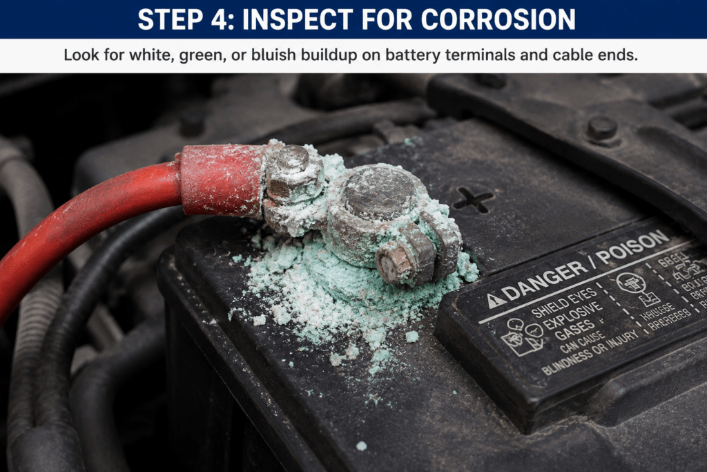
Step 4: Perform a Visual Inspection
Before any multimeter testing, physically inspect the system:
- Battery terminals and cables for looseness or corrosion
- Visible wiring for damage, chafing, or discoloration
- The alternator belt for wear, cracking, or looseness
- Ground straps and connection points for rust or corrosion
Step 5: Run Targeted Multimeter Tests
Once you have narrowed down the likely area, use the specific tests below: resistance testing for shorts, continuity testing for opens, voltage testing for power issues, voltage drop testing for weak connections, and ground testing for poor grounds.
Symptom to Diagnosis: What Test to Run for Each Warning Sign
Complete Symptom-to-Diagnosis Table
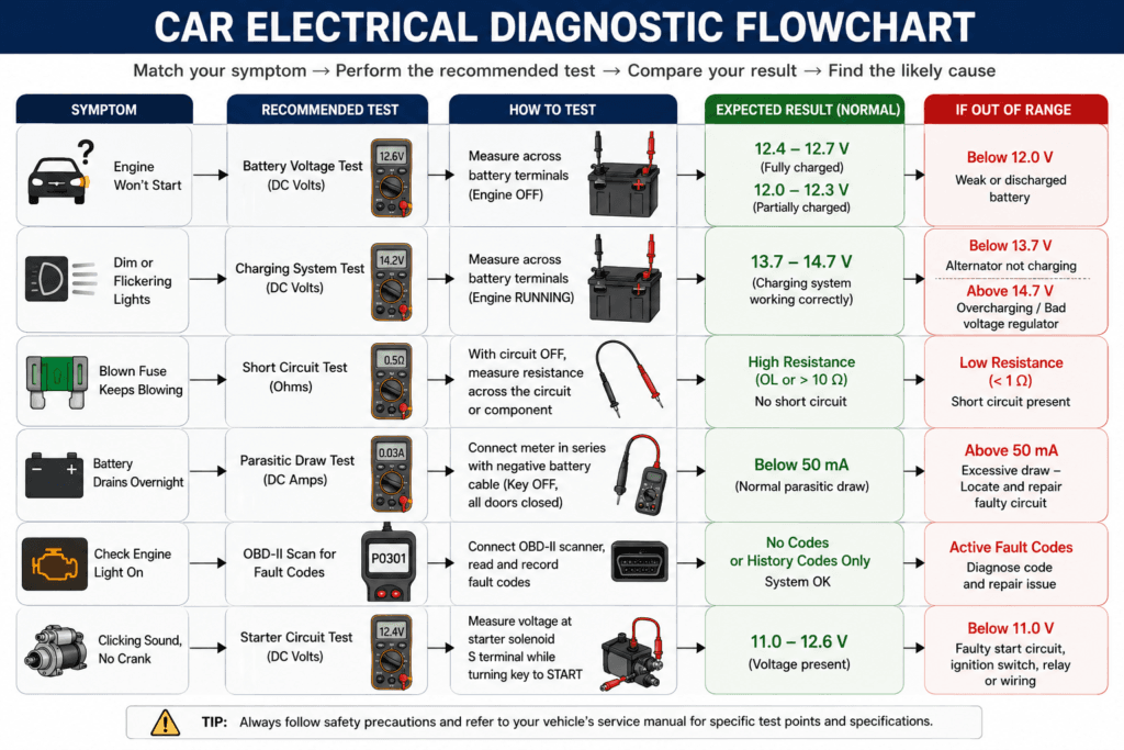
| Symptom | Likely Cause | Test to Run | Expected Healthy Reading |
|---|---|---|---|
| Flickering or dimming lights | Low voltage, failing alternator, corroded connection | Voltage test (engine running) | 13.7V to 14.7V at the battery |
| Repeatedly dead or weak battery | Weak battery, parasitic drain, alternator not charging | Voltage test (resting) plus parasitic draw test | 12.6V+ resting, under 50mA parasitic draw |
| Intermittent dashboard warning lights | Loose connector, poor ground, wiring fault | Continuity test plus ground test | Steady beep with no interruption when wiggling the harness |
| Burning smell or frequently blown fuses | Short circuit | Resistance test | Should not read near 0Ω unless expected for that circuit |
| Unresponsive electronic accessory | Open circuit or blown fuse | Continuity test | Beep confirms an unbroken path |
| Slow cranking or no-start | Weak battery, poor ground, corroded starter connection | Voltage drop test under cranking load | Under 0.5V drop across each major connection |
Flickering or Dimming Lights
This almost always points to a voltage problem, either the alternator is not producing enough output, or a corroded connection is dropping voltage before it reaches the lights. Start with a voltage test at the battery with the engine running.
Repeatedly Dead or Weak Battery
Test the resting voltage first. If it reads healthy but the battery still dies overnight, suspect a parasitic drain, something drawing power while the car is off. See our How to Measure Amps with a Multimeter guide for the full parasitic draw testing process.
Intermittent Dashboard Warning Lights
These are classic symptoms of a loose connector or a poor ground. Wiggle-test the wiring harness near the suspected component while watching a continuity test reading; an interruption in the beep as you wiggle the harness pinpoints the exact fault location.
Burning Smell or Frequently Blown Fuses
This is a short circuit until proven otherwise. Never simply replace the fuse with a higher-rated one to make the problem stop; this removes the circuit’s protection entirely and creates a genuine fire risk.
Unresponsive Electronic Accessories
Check the fuse first with a continuity test, then trace the circuit for an open connection if the fuse is good.
How to Test for a Short Circuit (Resistance Test)
What a Short Circuit Means
A short circuit occurs when current finds an unintended path, usually to ground, bypassing the component it is supposed to power. This typically causes a blown fuse and, left unaddressed, can cause overheating or fire.
Step by Step Resistance Test
- Disconnect the battery negative terminal to remove all power from the circuit
- Set your multimeter to resistance mode (Ω)
- Identify the circuit or component you suspect, and disconnect it from the rest of the harness if possible for an accurate isolated reading
- Touch one probe to each end of the suspected circuit
- Read the resistance value
Short Circuit Test Results Table
| Reading | What It Means |
|---|---|
| Matches the expected resistance for that component | Circuit is healthy |
| Near 0Ω where higher resistance is expected | Short circuit present; replace or repair the wiring |
| OL (open loop) | No short present, but check for an open circuit instead |
How to Test for an Open Circuit (Continuity Test)
What an Open Circuit Means
An open circuit means the electrical path is broken somewhere, so no current can flow at all. This causes the connected component to stop working entirely.
Step-by-Step Continuity Test
- Disconnect the battery to remove power from the circuit
- Set your multimeter to continuity mode
- Touch one probe to each end of the wire or component you are testing
- Listen for the beep
Open Circuit Test Results Table
| Result | What It Means |
|---|---|
| Beep | Circuit is complete; no open fault at this point |
| No beep, OL displayed | Open circuit confirmed, wire is broken or connection is disconnected |
| Beep only when wiggling the harness | Intermittent open, usually a loose connector pin |
💡 See our How to Test Continuity with a Multimeter guide for the complete continuity testing walkthrough.
How to Test for Low System Voltage
What Low Voltage Indicates
Low voltage anywhere in the system can stem from a weak battery, a failing alternator, or resistance in the wiring caused by corrosion or damage.
Step by Step Voltage Test
- Set your multimeter to DC voltage
- Test the battery at rest first, engine off, for at least a few minutes
- Start the engine and test again at the battery terminals
- If needed, test voltage at the specific component or connector in question
Voltage Test Results Table
| Test Point | Healthy Reading | Investigate If |
|---|---|---|
| Battery, resting | 12.6V or above | Below 12.2V |
| Battery, engine running | 13.7V to 14.7V | Reads the same as resting voltage or lower, suggests the alternator is not charging |
| Component or connector | Close to battery voltage minus a small, expected drop | Significantly lower than the source voltage |
How to Perform a Voltage Drop Test (Parasitic Drains and Weak Connections)
What Is Voltage Drop Testing?
Voltage drop testing measures how much voltage is lost across a connection while the circuit is active and under load, revealing high-resistance connections that a standard resistance test misses entirely.
A resistance test is performed with the circuit powered off and often shows a connection as “fine” because even a slightly corroded connection can still pass the small test current a multimeter sends during a resistance check. Under real load, that same connection can drop significant voltage, robbing the circuit of power without ever showing up as a complete open.
Why Voltage Drop Testing Finds What Other Tests Miss
This is why voltage drop testing is considered one of the most valuable diagnostic techniques for parasitic drains, corroded connections, and poor grounds. It tests the connection under the exact conditions where the problem actually occurs, not in an idealized, powered-off state.
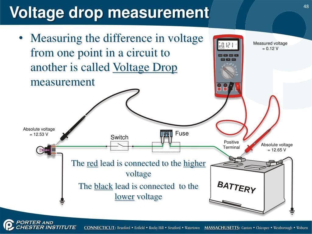
Step-by-Step Voltage Drop Test
- Set your multimeter to DC voltage
- Turn on the circuit you are testing so it is under normal operating load, for example, headlights on for a headlight circuit test
- Touch one probe on each side of the connection you want to test, such as the battery post and the cable clamp
- Read the voltage displayed, this is the voltage being lost, or dropped, across that specific connection
- Repeat at each connection point along the circuit to isolate exactly where the drop is occurring
Voltage Drop Results Table
| Connection Type | Healthy Voltage Drop | Investigate If |
|---|---|---|
| Battery terminal to cable | Under 0.2V | Above 0.2V, clean or replace the terminal connection |
| Ground strap or ground connection | Under 0.2V | Above 0.2V, corroded or loose ground |
| Switch contacts | Under 0.3V | Above 0.3V, worn or corroded switch |
| Full circuit segment under load | Under 0.5V total | Above 0.5V, isolate the specific bad connection |
How to Test Ground Connections
Why Poor Grounds Cause Intermittent Problems
A poor ground connection is one of the most common and most overlooked causes of intermittent electrical faults. Corrosion at a chassis ground point, a loose ground strap, or a poor engine-to-body ground can all cause symptoms that seem to come from a completely different part of the vehicle, sometimes appearing weeks after an unrelated repair disturbed the connection.
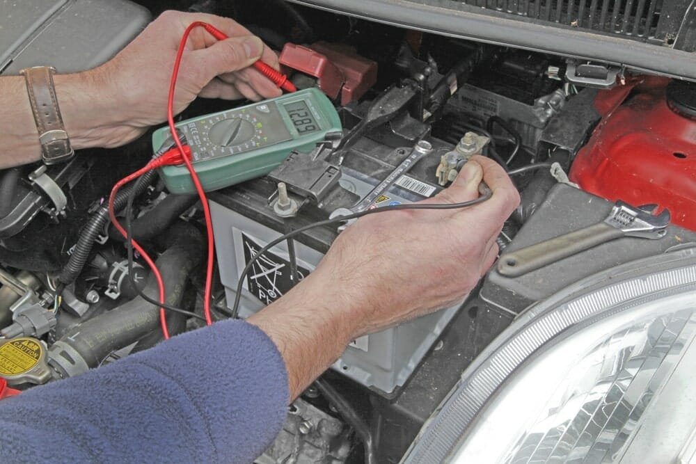
Step-by-Step Ground Test
- Turn on the circuit connected to the ground point you are testing, so it is under load
- Set your multimeter to DC voltage
- Touch one probe to the ground point itself and the other probe directly to the battery negative terminal
- Read the voltage difference between the two points
Ground Test Results Table
| Reading Between Ground Point and Battery Negative | What It Means |
|---|---|
| Close to 0V (under 0.2V) | Ground connection is healthy |
| 0.2V to 0.5V | Marginal, clean the connection |
| Above 0.5V | Poor ground, clean, tighten, or replace the ground strap or connection |
Common Electrical System Issues Caught by Diagnostics
Weak or Failing Battery Cells
A battery can pass a simple resting voltage check while still having a weak internal cell that fails under load. A load test catches this where a basic voltage check alone will not.
Faulty Alternators
An alternator not charging properly causes the battery to slowly discharge even while the car runs, eventually leaving you stranded. This is caught directly with the engine-running voltage test above.
Malfunctioning Sensors
Sensors like the oxygen sensor or mass airflow sensor can drift out of spec gradually, causing poor fuel economy and reduced performance long before triggering a warning light. Many sensor circuits can be checked with a basic voltage or resistance test against the manufacturer’s specification.
Corroded or Loose Connections
These are the classic source of intermittent faults and are exactly what voltage drop testing and ground testing are designed to catch.
Failing Control Modules
Modules controlling systems like ABS, airbags, or traction control can fail in ways that affect their specific system without an obvious external symptom, often requiring a scan tool to confirm rather than a multimeter alone.
DIY Diagnostics vs Professional Diagnostics: When to Call a Shop
What a Multimeter Can Diagnose Yourself
A multimeter handles the majority of common electrical issues: battery health, parasitic drains, short and open circuits, voltage drop across connections, and ground connection quality. These cover the vast majority of everyday car electrical problems.
When You Need a Professional Scan Tool Instead
Modern vehicles communicate internally over data networks like the CAN bus, and many control modules store manufacturer-specific fault codes that only a proper scan tool can read. If your multimeter tests all come back healthy but a warning light persists, or if the issue involves a specific control module rather than simple wiring, a scan tool diagnostic is the next step.
Signs You Should Stop and See a Technician
- Any work involving the airbag or SRS system, which can deploy unexpectedly if handled incorrectly
- Hybrid or electric vehicle high-voltage systems, which carry serious injury risk
- A persistent burning smell you cannot immediately locate and resolve
- An intermittent fault that resists every basic test in this guide after a genuine, thorough attempt
FAQ
What is included in a car electrical diagnostic?
A complete car electrical diagnostic includes checking battery health and resting voltage, testing alternator charging output, checking for short and open circuits, performing voltage drop tests on key connections, testing ground connections, and in professional settings, reading stored trouble codes with a scan tool. A DIY diagnostic with a multimeter covers most of these steps without specialized equipment.
How do I know if my car has an electrical problem?
Common warning signs include flickering or dimming lights, a battery that repeatedly goes dead, dashboard warning lights that come on intermittently, a burning smell or frequently blown fuses, and electronic accessories that stop responding. Any of these symptoms warrants running through the diagnostic process in this guide, starting with a battery voltage check.
Can I do an electrical system diagnosis myself with a multimeter?
Yes, for the majority of common issues. A multimeter handles battery testing, short circuit detection through resistance testing, open circuit detection through continuity testing, voltage drop testing for weak connections, and ground connection testing. Issues involving specific control module fault codes or modern communication networks may require a professional scan tool in addition to your multimeter.
What is voltage drop testing and why does it matter?
Voltage drop testing measures how much voltage is lost across a connection while the circuit is powered on and under load. It catches corroded or high-resistance connections that a standard resistance test, performed with the circuit off, can miss entirely, since even a partially corroded connection can still pass a multimeter’s small test current. A healthy connection should drop under 0.2V under load, with a full circuit segment under 0.5V total.
How do I test a ground connection in my car?
Turn on the circuit connected to the ground point so it is under load. Set your multimeter to DC voltage. Touch one probe to the ground point and the other directly to the battery negative terminal. A reading close to 0V, under 0.2V, indicates a healthy ground. A reading above 0.5V indicates a poor ground connection that needs cleaning, tightening, or repair.
Why does electrical diagnosis always start with the battery?
A weak or discharged battery produces unstable voltage throughout the entire electrical system, making every other diagnostic test unreliable. Confirming the battery reads 12.6V or above at rest, and charging it fully if it does not, ensures that any further test results you gather accurately reflect the actual fault rather than being skewed by inadequate battery power.
Conclusion
A complete car electrical diagnostic follows a consistent process regardless of the specific symptom you are chasing: confirm the battery is healthy first, identify and observe the symptoms, perform a visual inspection, then run targeted multimeter tests to isolate the exact fault.
The tests most guides skip, voltage drop testing and ground connection testing, are often the ones that find what a simple voltage or resistance check misses entirely. A connection that passes a basic resistance test with the power off can still be silently dropping voltage and starving a circuit the moment it is put under real load.
Work through the symptom-to-diagnosis table first to narrow your search, then use the specific step-by-step test that matches your situation. Most electrical problems that seem mysterious turn out to have a straightforward, findable cause once tested systematically.
2 thoughts on “Car Electrical Diagnostic: Complete Step-by-Step Guide to Electrical System Diagnosis”