You are holding a multimeter, but the dial makes no sense. Numbers, letters, random shapes, and you have no idea which one to turn it to.
Multimeter symbols are shorthand codes that tell the meter what to measure: voltage, current, resistance, continuity, and more. Once you know what each one means, setting up a multimeter takes about 10 seconds.
This guide covers every symbol on a multimeter in plain English. No electronics degree needed. Find your symbol, get your answer, and get back to work.
Quick Reference Chart: Every Multimeter Symbol
Bookmark this table. It is the only reference you will need.

| Symbol | Name | What It Means | When to Use It |
|---|---|---|---|
| V~ | AC Voltage | Voltage from alternating current | Wall outlets, extension cords, mains appliances |
| V⎓ | DC Voltage | Voltage from direct current | Car batteries, phone chargers, solar panels |
| Ω | Resistance | How much a material resists current flow | Checking resistors, testing wire condition |
| A⎓ | DC Current | Direct current flowing through a circuit | Measuring current draw in car circuits, electronics |
| A~ | AC Current | Alternating current flowing through a circuit | Measuring current in mains-powered devices |
| ))) | Continuity | Checks if a circuit is complete | Testing wires, fuses, and switches |
| →| | Diode | Tests diode direction and forward voltage drop | Checking diodes in electronics repair |
| -||- | Capacitance | Measures how much charge a capacitor holds | Testing capacitors in circuit boards |
| Hz | Frequency | Measures cycles per second | Checking motors, generators, and signal outputs |
| hFE | Transistor Gain | Tests transistor amplification factor | Diagnosing transistors in circuits |
| NCV | Non-Contact Voltage | Detects live voltage without touching wires | Quickly checking if a wire is live safely |
| °C / °F | Temperature | Measures temperature with a probe | Checking component or HVAC temperature |
| OL | Overload | Reading exceeds the selected range | Switch to a higher range immediately |
| CAT I/II/III/IV | Safety Rating | Maximum voltage category the meter is rated for | Always match to your working environment |
💡 Two symbols you will use 90% of the time: V⎓ for DC voltage (batteries, car circuits) and ))) for continuity (checking wires and fuses). Start there.
Voltage Symbols on a Multimeter (ACV, DCV, VAC, VDC)
Voltage is what you will measure most often. The confusing part is that different multimeter brands label the same setting differently.
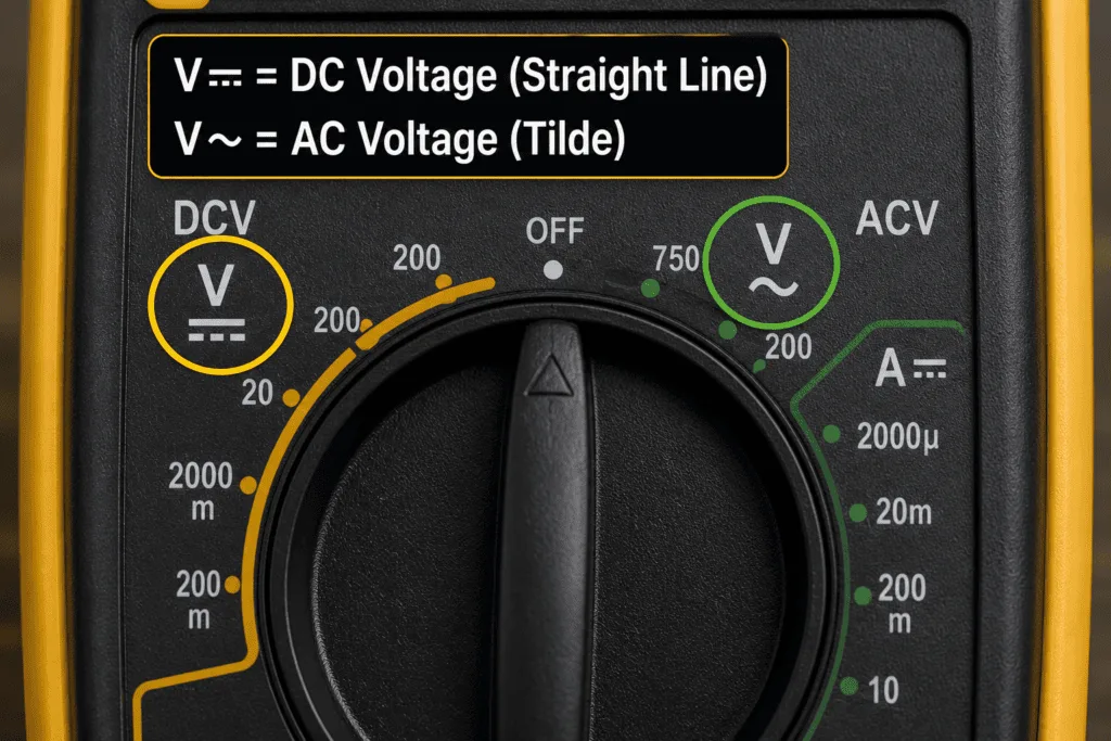
AC Voltage: V~, ACV, or VAC
V~, ACV, and VAC all mean the same thing: your multimeter is set to measure alternating current voltage.
Use this setting for anything powered by a wall outlet plug, light switches, extension leads, or mains-powered appliances. In most homes that means 110 to 125V (US) or 220 to 240V (UK, EU, Pakistan).
⚠️ Safety first: AC voltage from a wall outlet can kill. Double check your probe connections before you touch anything live.
The AC symbol is a tilde (~) or a small wave line because AC power flows in waves rather than a straight line.
DC Voltage: V⎓, DCV, or VDC
V⎓, DCV, and VDC all mean the same thing: your multimeter is set to measure direct current voltage.
Use this setting for car batteries, phone chargers, USB ports, solar panels, and anything running on batteries. If it uses a battery or a DC adapter, this is your setting.
The DC symbol is a straight solid line with a dashed line beneath it, because DC power flows in one constant direction.
💡 Quick rule: Wall outlet equals V~. Battery or car equals V⎓. That covers 90% of what most people test.
What Is the Difference Between AC and DC Voltage?
AC voltage constantly reverses direction. It is what comes out of your wall. DC voltage flows in one steady direction. It is what batteries produce. Your multimeter measures both, but you have to tell it which one you are dealing with first. Pick the wrong setting and you will get a zero reading or, on some older meters, a blown fuse.
Current Symbols on a Multimeter (DCA, ACA, mA, μA)
Current symbols trip people up more than any other setting, mostly because of one mistake that blows the multimeter fuse almost every time.
DC Current: A⎓ or DCA
A⎓ and DCA mean the same thing: your multimeter is set to measure direct current flowing through a circuit.
Use this when measuring current draw in car circuits, battery-powered electronics, LED strips, or anything running off DC power. Unlike voltage testing, current measurement requires you to break the circuit and put the multimeter in series so the current actually flows through the meter.
AC Current: A~ or ACA
A~ and ACA mean the same thing: your multimeter is measuring alternating current through a circuit.
Many basic multimeters do not include this setting. If yours does not have it, that is normal. AC current measurement is less common in everyday testing and usually calls for a clamp meter instead.
mA and μA: Milliamps and Microamps
This is where most beginners make a costly mistake.
mA (milliamps): One thousandth of an amp. Used for measuring small currents in low-power electronics, sensors, and microcontrollers.
μA (microamps): One millionth of an amp. Used for ultra-low power circuits like certain medical devices or precision electronics.
The critical thing to understand is that your multimeter has a separate input port for mA and μA. It is not the same port as the regular A setting.
⚠️ Golden rule: Always check which port your red probe is plugged into before measuring current. Wrong port means a blown fuse, no exceptions.
Resistance Symbol (Ω) and Continuity Symbol on a Multimeter
Two of the most used settings on any multimeter. One measures how much a component resists current. The other tells you instantly if a circuit is complete or broken.
Resistance: The Omega Symbol (Ω)
Ω is the Greek letter Omega, and on a multimeter it means resistance, measured in ohms.
Use this setting to check resistors, test whether a wire has resistance it should not have, or verify component values on a circuit board. The lower the number, the less resistance. A reading of zero means no resistance at all, and current flows freely.
Most multimeters give you multiple Ω ranges: 200Ω, 2kΩ, 20kΩ, and so on. If you see OL on the display, the resistance is higher than your selected range, so switch up to the next one.
Continuity Symbol: What Does It Look Like?
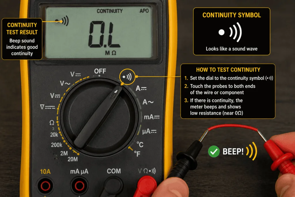
The continuity symbol is one of two things, depending on your brand, and both mean the same setting:
- ))) a sound wave icon, most common on Fluke, Klein, and most digital meters
- →| a diode arrow symbol, used on some budget and mid-range meters where continuity and diode test share one dial position
In plain English, continuity mode checks if electricity can flow from point A to point B without interruption. No broken wire, no blown fuse, no faulty switch. Just a complete path or not.
💡 On many meters the Ω and continuity symbol share the same dial position. Press the function button once you have selected it to toggle between the two.
What Does a Beep Mean on a Multimeter?
The beep means the circuit is complete and current can flow between the two points you are testing.
That is all it tells you. It does not tell you the resistance value. It does not tell you the wire is in good condition. It simply confirms a connection exists. No beep means the circuit is open, something is broken, disconnected, or blown somewhere between your two probes.
⚠️ Important: A beep confirms continuity, not quality. A wire can beep and still have high resistance that causes problems under load. For full confidence follow up with an Ω resistance reading too.
Diode Symbol on a Multimeter: What It Means and When to Use It
The diode symbol looks like an arrow pointing into a vertical line, →|, and it tests whether a diode is working correctly and allowing current to flow in the right direction.
Most beginners will not use this setting often. But knowing what the symbol means stops you from accidentally selecting it when you meant to use continuity mode.
💡 Worth knowing: On most multimeters the diode symbol and the continuity symbol share the exact same dial position. One press selects continuity, press again and it switches to diode test mode.
How to Use the Diode Test Setting
Using the diode test is straightforward:
- Red probe goes to the anode (positive side of the diode)
- Black probe goes to the cathode (negative side, marked with a line or band)
A healthy silicon diode shows a forward voltage drop between 0.5V and 0.8V. Germanium diodes typically read lower, between 0.2V and 0.3V. Current flows one way, as it should.
A faulty diode shows one of two things: OL in both directions (open circuit, the diode is blown) or a reading close to 0V in both directions (short circuit, the diode is shorted). Either way, the diode needs replacing.
Unlike continuity mode, the diode test gives you a voltage number rather than just a beep.
Capacitance Symbol on a Multimeter
The capacitance symbol looks like two parallel lines facing each other, -||-, representing the two plates inside a capacitor.
It measures how much electrical charge a capacitor can store, displayed in farads (F), microfarads (μF), or nanofarads (nF).
If you cannot find this symbol on your multimeter, that is completely normal. You have not missed it.
Which Multimeters Have a Capacitance Setting?
| Price Range | Capacitance Included? |
|---|---|
| Budget meters under $20 | Rarely included |
| Mid-range meters ($30 to $80) | Some include it, some do not |
| Professional meters ($80+) | Almost always included |
If capacitance testing matters for your work electronics repair, checking old capacitors on circuit boards, or HVAC diagnostics it is worth upgrading to a meter that includes it. For most beginners doing basic home or car electrical checks, you will not need it.
Other Multimeter Symbols: NCV, HFE, Hz, and OL Explained
These symbols are searched for constantly because most guides never bother to explain them.
NCV: Non-Contact Voltage Detector
NCV on a multimeter means Non-Contact Voltage. It detects live voltage in a wire without you touching the wire at all.
Point the multimeter’s tip near a cable, socket, or switch. If voltage is present, the meter beeps or flashes. No probes, no contact, no risk. It is the fastest safety check in electrical work. Use it before touching any wire you are not 100% sure is dead.
hFE: Transistor Gain Test
hFE on a multimeter measures transistor gain, specifically how much a transistor amplifies current.
You will only use this if you work with electronics at the component level. If your meter has a small socket panel labeled hFE with holes marked B, C, and E, that is where the transistor legs plug in for testing.
Hz: Frequency Measurement
Hz on a multimeter measures frequency, how many times per second an electrical signal completes a full cycle.
Use it for checking motors, generators, inverters, and signal outputs. Standard mains power runs at 50Hz (UK, EU, Pakistan) or 60Hz (US). If your Hz reading is far off those numbers on a mains circuit, something is wrong.
OL: What Does OL Mean on a Multimeter?
OL means Overload. The value you are measuring is higher than the range you have selected.
That is it. It is not a fault with the meter, and it is not a fault with the circuit. Simply switch to a higher range and measure again.
Example: Testing a 240V outlet on the 200V range shows OL instantly. Switch to the 600V range, and the correct reading appears.
CAT Ratings on a Multimeter: What Do They Mean?
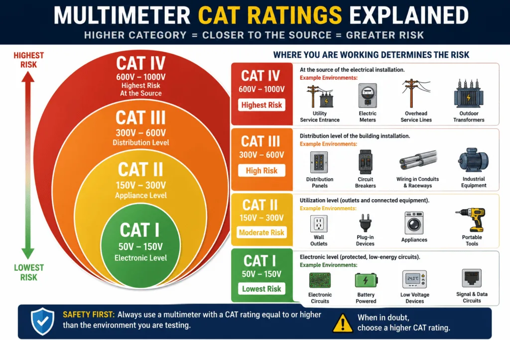
CAT stands for Category. It is a safety rating that tells you the maximum electrical environment your multimeter is designed to handle safely.
The higher the CAT number, the more dangerous the electrical environment it can safely protect you in. Using a low-rated meter in a high-energy environment is not just a bad reading; it is a genuine safety risk.
CAT Rating Reference Table
| CAT Rating | Environment | Typical Use |
|---|---|---|
| CAT I | Low-voltage electronics | Circuit boards, battery packs, signal testing |
| CAT II | Household outlets and appliances | Wall sockets, extension leads, plug-in devices |
| CAT III | Fixed building wiring | Consumer units, distribution panels, hard-wired circuits |
| CAT IV | Utility and industrial supply | Electricity meters, outdoor supply lines, industrial feeds |
CAT I: Low Voltage Electronics
CAT I covers low-energy, low-voltage work such as circuit boards, battery packs, and signal testing. The electrical energy here is limited, so the risk of a dangerous fault is minimal. Most electronics hobbyists work at this level.
CAT II: Household Appliances and Sockets
CAT II covers standard household outlets and plug-in appliances, the most common environment for home DIYers. Testing a wall socket, checking a lamp, or measuring voltage at a plug puts you in CAT II territory. Any multimeter used for home electrical work should be rated CAT II at minimum.
CAT III: Fixed Building Wiring
CAT III covers fixed building installations, consumer units, distribution boards, hard-wired lighting circuits, and three-phase wiring. The energy available here is significantly higher than at a wall socket. If you are working at a fuse board or testing fixed wiring you need a CAT III-rated meter.
CAT IV: Utility and Industrial Supply
CAT IV covers the highest energy environments, such as electricity supply meters, outdoor utility feeds, and industrial power systems. This is professional electrician and utility worker territory. The fault energy at this level can be lethal. Only use a CAT IV-rated multimeter if your work genuinely requires it.
🔧 Recommendation for home DIY users: A CAT II or CAT III multimeter covers everything you will realistically encounter — wall sockets, appliances, consumer units, and car electrics. Do not go below CAT II for anything involving mains voltage.
FAQ
What is the continuity symbol on a multimeter?
The continuity symbol is either a sound wave icon ())) or a diode arrow →| sharing the same dial position, depending on your brand. Select it, touch your probes to both ends of a wire or component, and listen. A beep means the circuit is complete. No beep means something is broken.
What do ACV and DCV mean on a multimeter?
ACV means alternating current voltage, used for testing wall outlets, mains-powered appliances, and light switches. DCV means direct current voltage, used for testing car batteries, phone chargers, and anything battery-powered. Always confirm which one you are dealing with before selecting a setting.
What does OL mean on a multimeter?
OL means Overload. The reading exceeds the range you have currently selected. It is not a fault with the meter and not a fault with the circuit. Simply switch to the next higher range and measure again.
What does NCV mean on a multimeter?
NCV means Non-Contact Voltage, which detects live electrical voltage without your probes ever touching the wire. Hold the meter tip near any cable or socket. A beep or light means voltage is present. It is the fastest and safest way to check if something is live before you work on it.
Why doesn’t my multimeter have a capacitance symbol?
Not every multimeter includes it, and that is completely normal. Budget meters under $20 rarely have a capacitance setting. Mid-range meters sometimes do. If your dial does not show the -||- symbol your meter simply was not built with that function.
What CAT rating do I need for home use?
For standard home DIY work — testing wall sockets, checking appliances, measuring car battery voltage — a CAT II or CAT III rated multimeter is everything you need. CAT II covers outlets and plug-in devices. CAT III covers consumer units and fixed wiring. Never use a CAT I meter on mains voltage.
Conclusion
Multimeter symbols look intimidating for about five minutes, and then they never confuse you again.
Remember the two you will use most: V⎓ for anything battery-powered, and the sound wave symbol for continuity checks on wires, fuses, and switches. Everything else on the dial becomes useful the moment a specific job calls for it.
Keep this chart bookmarked. The next time you are staring at an unfamiliar symbol, you will have your answer in seconds instead of guessing.