Your solar panel is supposed to be charging your battery, but nothing is happening. Your 12V power supply feels warm, but your device won’t turn on. Your power bank shows a full charge but dies in minutes.
Before buying replacements, grab your multimeter. Most solar panel and power supply problems can be diagnosed in under five minutes with a basic digital multimeter.
This guide shows you exactly how to test a solar panel voltage and current output, how to test a 12V power supply, and how to check a power bank, all with the same affordable tool.
Safety First: Before You Test Anything
Solar panels generate electricity in any light condition. Even on a cloudy day, a solar panel can produce enough voltage to cause a shock. Follow these rules before touching anything.
⚠️ Warning: Solar panels cannot be switched off. They produce voltage whenever light hits them. Always use insulated probes and never touch bare terminals with bare hands.
Key safety rules:
- Wear insulated rubber gloves when handling solar panel terminals
- Never test in rain or wet conditions — water and electricity are dangerous
- Disconnect the panel from the charge controller and battery before testing
- Never short the positive and negative terminals directly — always connect through your multimeter
- Inspect cables and connectors for damage before starting
What You Need Before You Start
- A digital multimeter with DC voltage (V—) and DC (A—) settings
- Red and black test leads
- Insulated rubber gloves
- A clear sunny day for solar panel testing
How to Set Up Your Multimeter for Solar and Power Testing
For voltage tests:
- Plug black probe into COM port
- Plug red probe into VΩ port
- Turn dial to DC voltage (V—) mode
- Select 200V range or use auto-range
For current tests:
- Plug black probe into COM port
- Plug red probe into the 10A port (not the VΩ port)
- Turn dial to DC (A—) mode
- Select the 20A range
⚠️ Critical: Always move the red probe to the 10A port before measuring current. Measuring current through the VΩ port will instantly blow your multimeter fuse.
How to Test Solar Panel Voltage (VOC Test)
What Is Open Circuit Voltage (VOC)?
Open circuit voltage (VOC) is the maximum voltage a solar panel produces when no load is connected. It is the first and most important test for diagnosing solar panel health.
Every solar panel has a rated VOC printed on its specification label on the back. A healthy panel under full sun should produce close to this rated value.
What Multimeter Setting to Use for Solar Panel Voltage
Set your multimeter to DC voltage mode (V—). Solar panels produce direct current; never use the AC voltage setting.
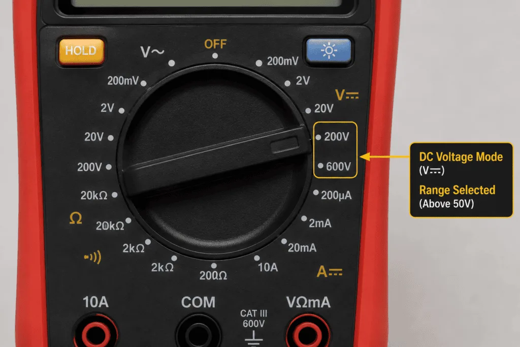
Select a range higher than your panel’s rated VOC:
- Most 12V residential panels: rated 18V to 22V VOC — use 200V range
- Most 24V panels: rated 36V to 44V VOC — use 200V range
- Large grid-tie panels: rated 30V to 50V VOC — use 200V range
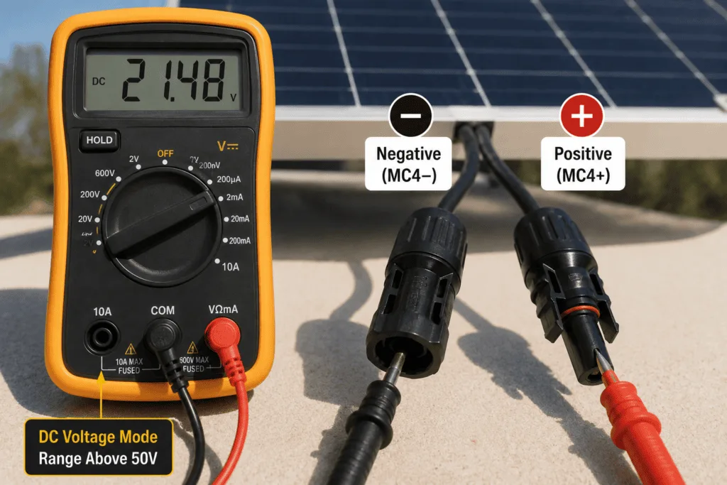
Step-by-Step Solar Panel Voltage Test
- Disconnect the solar panel from the charge controller and battery
- Position the panel in direct, unobstructed sunlight
- Set your multimeter to DC voltage mode (V—)
- Connect the red probe to the positive terminal (marked + or red)
- Connect the black probe to the negative terminal (marked – or black)
- Read the voltage on the display
- Compare to the rated VOC on the panel label
Solar Panel Voltage Results Table
| Measured VOC vs Rated VOC | What It Means | What to Do |
|---|---|---|
| Within 0 to 15% below rated | Normal — panel is healthy | No action needed |
| 15 to 25% below rated | Possible shading, dirt, or mild degradation | Clean panel, check for shade, retest |
| More than 25% below rated | Cell damage or internal wiring fault | Inspect for cracks, discoloration, test individual cells |
| 0V or near zero | No output — panel may be completely failed | Check connections, test in brighter light, consider replacement |
| Above rated VOC | Normal in cold temperatures — panels produce higher voltage when cold | No action needed |
Example: A panel rated 20V VOC should read between 17V and 20V under good sunlight. A reading of 10V or below suggests a serious problem.
How to Test Solar Panel Current (ISC Test)
What Is Short Circuit Current (ISC)?
Short circuit current (ISC) is the maximum current a solar panel produces when the positive and negative terminals are connected directly through a very low resistance path — in this case through your multimeter on the current setting.
ISC testing tells you how much actual current your panel can deliver. Combined with the VOC test, it gives you a complete picture of panel health.
What Multimeter Setting to Use for Solar Panel Current
Set your multimeter to DC mode (A—). Move the red probe to the 10A port before connecting to the panel.
⚠️ Important: Take the ISC reading quickly — within 2 to 3 seconds. Prolonged short circuit conditions are not harmful to the panel but most budget multimeters are not rated for continuous solar current. Always check that your multimeter’s 10A port can handle the expected current before testing.
Step-by-Step Solar Panel Current Test
- Disconnect the panel from all system components
- Move the red probe from the VΩ port to the 10A port
- Set the dial to DC (A—) on the 20A range
- Position the panel in full direct sunlight
- Connect the red probe to the positive terminal
- Connect the black probe to the negative terminal
- Read the current quickly within 2 to 3 seconds
- Compare to the rated ISC on the panel label
Solar Panel Current Results Table
| Measured ISC vs Rated ISC | What It Means | What to Do |
|---|---|---|
| Within 0 to 15% below rated | Normal — current is healthy | No action needed |
| 15 to 30% below rated | Possible shading, dirty panel, or thin cloud cover | Clean panel, remove shading sources, retest on clearer day |
| More than 30% below rated | Cell damage, bypass diode failure, or severe degradation | Inspect cells closely, compare to other panels in same conditions |
| 0A | No current output | Check connections, verify probe is in 10A port, retest |
Note: Current is more sensitive to light conditions than voltage. Even thin cloud cover significantly reduces current. Always test on the clearest day possible for the most accurate ISC reading.
How to Calculate Solar Panel Wattage Output
What Is Wattage and Why Does It Matter?
Wattage is the actual usable power your solar panel delivers. It is calculated using a simple formula:
Watts = Volts multiplied by Amps (W = V x A)
However, the VOC and ISC values are maximum theoretical values measured under specific conditions. Real-world wattage under load is typically 70 to 90% of the theoretical maximum.
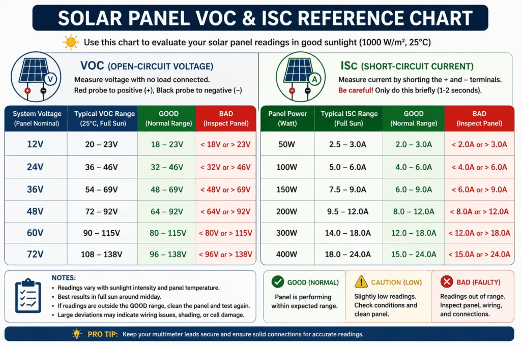
Solar Panel Voltage and Current Reference Chart
| Panel Rating | Normal VOC Range | Normal ISC Range | Estimated Real Wattage |
|---|---|---|---|
| 50W panel | 17V to 22V | 2.5A to 3.5A | 40W to 48W |
| 100W panel | 18V to 22V | 5A to 7A | 80W to 95W |
| 200W panel | 20V to 26V | 8A to 11A | 160W to 190W |
| 300W panel | 32V to 40V | 8A to 10A | 240W to 285W |
How to Know If Your Solar Panel Is Underperforming
Calculate the theoretical wattage from your VOC and ISC readings and compare to the rated wattage on the label. A healthy panel should produce 75 to 90% of rated wattage under good real-world conditions.
If your panel produces less than 70% of rated wattage consistently under clear sky conditions the panel is underperforming and needs further investigation.
Signs of a Bad or Underperforming Solar Panel
Voltage Significantly Below Rated VOC
A reading more than 25% below rated VOC indicates cell damage, internal wiring failure, or severe degradation. Check the panel surface for:
- Cracks in the glass (even hairline cracks)
- Brown or yellow discoloration on cells (hot spots)
- Bubbling or delamination of the protective layers
- Silver or gray snail trail lines across cells
Current Output Lower Than ISC Rating
A reading consistently 30% or more below rated ISC under clear sunlight suggests:
- Partial shading from a nearby object that has grown or been built
- Dirty surface from dust, pollen, or bird droppings
- Failed bypass diodes inside the panel
- Internal cell damage not visible from the outside
Visible Physical Damage Signs
| Sign | What It Means |
|---|---|
| Cracks in glass or backsheet | Moisture can enter — cell damage will worsen |
| Brown or yellow hot spots | Overheating — dead or dying cells |
| Burn marks near junction box | Arcing or loose connection — fire risk |
| Bubbling or peeling layers | Adhesive failure — moisture intrusion |
| Snail trails across cells | Moisture penetration — performance will decline |
How to Test a 12V Power Supply with a Multimeter
What Is a 12V Power Supply?
A 12V DC power supply converts AC mains voltage into 12V DC. It is used to power routers, CCTV systems, LED strips, car accessories, and many electronic devices. When a 12V power supply fails, it usually stops outputting the correct voltage.
Signs of a Bad 12V Power Supply
- Device powered by the supply stops working
- Supply gets very hot during normal use
- Supply makes a buzzing or whining sound
- Device works on battery but not on the supply
- Supply voltage indicator light is off
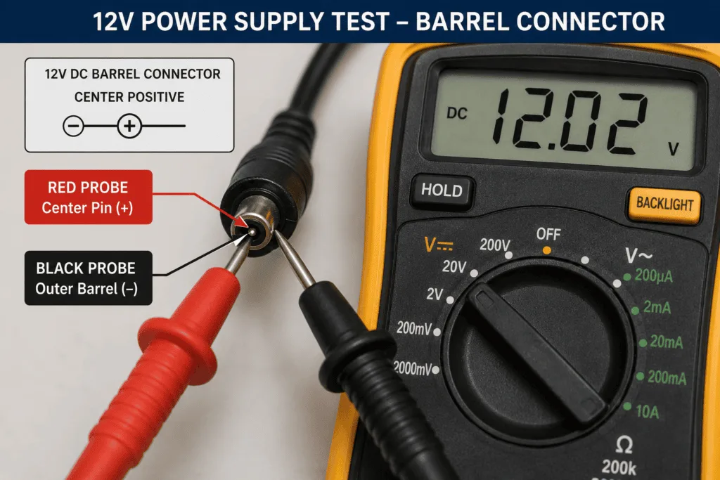
Step-by-Step 12V Power Supply Test
- Plug the power supply into the wall outlet
- Do not connect it to the device yet
- Set your multimeter to DC voltage mode (V—) on the 20V range
- Insert the red probe into the center of the barrel connector (positive)
- Touch the black probe to the outer barrel of the connector (negative)
- Read the voltage on the display
- Compare to the rated output voltage on the supply label
12V Power Supply Results Table
| Reading | What It Means | What to Do |
|---|---|---|
| Within 5% of rated voltage (11.4V to 12.6V) | Power supply is working correctly | No action needed |
| Below 11V | Supply is failing or overloaded | Test without load connected, then replace if still low |
| 0V | No output — supply has failed | Check wall outlet first, then replace supply |
| Above 13V | Supply is over-volting | Replace immediately — risk of device damage |
How to Test a Power Bank with a Multimeter
What Is a Power Bank?
A power bank is a portable battery that stores electrical energy and charges devices through USB ports. A failing power bank may show a full charge indicator but deliver very little actual current or voltage to the device being charged.
Signs of a Failing Power Bank
- Device charges very slowly despite power bank showing full charge
- Power bank capacity drops to zero faster than expected
- Power bank gets unusually hot during charging or discharging
- Device shows charging but battery percentage does not rise
Step-by-Step Power Bank Test
- Ensure the power bank is fully charged
- Set your multimeter to DC voltage mode (V—) on the 20V range
- Touch the red probe to the positive pin of the USB output port (the pin on the right when the USB port faces you)
- Touch the black probe to the ground pin (the pin on the left)
- Read the voltage on the display
- For current testing, move the red probe to the 10A port, set to DC (A—), and connect a USB load device to measure actual output current
Power Bank Test Results Table
| Test | Good Reading | Bad Reading |
|---|---|---|
| USB output voltage (no load) | 4.75V to 5.25V | Below 4.5V or above 5.5V |
| USB output voltage (under load) | 4.5V to 5.1V | Drops below 4V under load |
| USB output current (with device charging) | 0.5A to 2.4A depending on device | Below 0.3A means weak output |
| No voltage reading | Power bank has failed internally | Replace the power bank |
💡 Tip: A power bank that shows 5V at the USB port but delivers very low current has a failing internal battery or protection circuit. The voltage looks correct but it cannot sustain output under load.
Interpreting Your Readings: Complete Reference Chart
Solar Panel Reading Reference Chart
| Test | Normal Reading | Investigate If |
|---|---|---|
| VOC (open circuit voltage) | Within 15% of rated VOC | More than 25% below rated VOC |
| ISC (short circuit current) | Within 15% of rated ISC | More than 30% below rated ISC |
| Wattage (V x A) | 75 to 90% of rated watts | Below 70% of rated watts |
Power Supply Reading Reference Chart
| Device | Normal Output Voltage | Bad Reading |
|---|---|---|
| 12V DC power supply | 11.4V to 12.6V | Below 11V or above 13V |
| 5V USB power bank | 4.75V to 5.25V | Below 4.5V or above 5.5V |
| 9V DC adapter | 8.55V to 9.45V | Below 8V or above 10V |
| 19V laptop charger | 18V to 20V | Below 17V or above 21V |
What to Do When Readings Are Outside Normal Range
For solar panels: Clean the panel surface first. Remove any shading sources. Retest on the clearest day possible. If readings are still significantly below rated values, inspect the panel visually for cracks, hot spots, or delamination. A panel producing less than 70% of rated output consistently should be considered for replacement.
For 12V power supplies: Test with no load connected first. If voltage is still low or zero, the supply has failed and needs replacing. Power supplies are generally not repairable — replacement is the most cost-effective solution.
For power banks: Test under load by connecting a charging device. If voltage drops significantly under load or current output is very low the internal battery has degraded, and the power bank needs replacing.
FAQ
What voltage should a solar panel read on a multimeter?
A solar panel should read close to its rated open circuit voltage (VOC) printed on the specification label on the back. Most 100W panels read between 18V and 22V under full sunlight. A reading within 15% of the rated VOC is considered normal. A reading more than 25% below rated VOC indicates a problem with the panel.
How do I test solar panel current with a multimeter?
Move the red probe to the 10A port on your multimeter. Set the dial to DC current (A—) on the 20A range. Connect the red probe to the positive terminal and the black probe to the negative terminal of the disconnected solar panel. Read the current quickly within 2 to 3 seconds. Compare to the rated ISC on the panel label.
What should a 12V power supply read on a multimeter?
A healthy 12V power supply should read between 11.4V and 12.6V on a multimeter set to DC voltage mode. Insert the red probe into the center of the barrel connector and touch the black probe to the outer barrel. A reading below 11V or of 0V means the supply has failed and needs replacing.
How do I know if my solar panel is bad?
Test the VOC voltage with your multimeter. A reading more than 25% below the rated VOC suggests a problem. Also check for visible damage — cracks in the glass, brown hot spots, bubbling layers, or burn marks near the junction box. A panel consistently producing less than 70% of its rated wattage under clear sky conditions should be replaced.
Can I test a power bank with a basic multimeter?
Yes. Set your multimeter to DC voltage mode and touch the probes to the USB output pins. A healthy power bank reads between 4.75V and 5.25V. For a current test move the red probe to the 10A port, set to DC amps, and connect a charging device. Low current output under load indicates a failing internal battery.
What is the difference between VOC and ISC on a solar panel?
VOC (open circuit voltage) is the maximum voltage the panel produces when no load is connected. ISC (short circuit current) is the maximum current the panel produces when the terminals are connected directly through a very low resistance path. VOC tells you if the cells are generating voltage. ISC tells you if the cells are generating current. Together, the two tests give you a complete picture of panel health.
Conclusion
Testing a solar panel, 12V power supply, or power bank with a multimeter takes less than five minutes and can save you from expensive unnecessary replacements.
For solar panels, always test VOC voltage first. A reading close to the rated VOC means the panel is generating voltage correctly. Then test ISC current. Both readings together tell you how healthy the panel is and let you calculate approximate wattage output.
For 12V power supplies, test the DC voltage at the barrel connector. A reading within 5% of the rated voltage means the supply is working. For power banks, check the USB output voltage under load; a voltage drop under load reveals a failing battery.
Always disconnect solar panels from the charge controller before testing. Always use the correct multimeter port for current measurements. And always wear insulated gloves when handling solar panel terminals.
1 thought on “How to Test a Solar Panel and Power Supply with a Multimeter”