A circuit board can look perfect and still be wrong. A resistor can be the wrong value. A diode can be turned around. A tiny solder bridge can short two pins under a chip. None of these faults show up until someone tests the board.
In an electronics factory, that test is usually done by an ICT tester. It checks every part on the board, one at a time, in less than a minute.
In this guide, I explain what an ICT tester is, how a PCB in-circuit test works, what it can and cannot find, and how it compares with flying probe and functional testing. I also show which parts of an in-circuit test you can copy at home with a multimeter.
Quick answer: An ICT tester (in-circuit tester) is a machine that checks an assembled circuit board for manufacturing faults. It presses hundreds of spring-loaded pins, called a bed of nails, onto test points on the board. It then measures each part on its own: shorts, opens, resistor and capacitor values, diode direction, and missing or wrong parts. A typical test takes less than a minute per board.
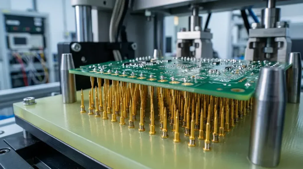
underside of the board at once, so an ICT tester can check every
component in a single pass.
What Is an ICT Tester?
ICT stands for in-circuit test. An ICT tester is automatic test equipment that checks a printed circuit board assembly (PCBA) after the parts are soldered on. “In-circuit” means each part is measured while it is still soldered into the circuit. Nothing is removed from the board.
An ICT tester has three main parts:
- The test system. A cabinet full of switching and measurement cards, run by a computer. Large systems have thousands of test channels. Keysight’s i3070 Series 7i, for example, supports up to 5,760 test nodes, according to I-Connect007.
- The fixture. A custom plate with spring-loaded pins, often called pogo pins, placed to match the test points of one board design. Vacuum or a mechanical press pulls the board down onto the pins.
- The test program. Software that knows every part on the board and the value each one should read.
In schools and offices, ICT also stands for information and communication technology. This guide covers only the electronics meaning.
What Does “ICT Circuit” Mean?
When people say “ICT circuit,” they usually mean one of two things. The first is the board being tested, which engineers call the unit under test (UUT). The second is the measuring circuit inside the tester that isolates each part, which I explain in the next section.
Either way, one rule matters most. Every net on the board needs a test point that a pin can reach. A net with no test point cannot be tested by a bed-of-nails ICT tester.
How an ICT Tester Works
A PCB in-circuit test runs in a fixed order. The safe, unpowered tests come first, so a shorted board never gets power.
- Load the board. The operator places the board on the fixture. Vacuum or a press pulls it down onto the pins.
- Check pin contact. The tester confirms that each pin is actually touching its test point.
- Test for shorts and opens (power off). It checks every net against the others for solder bridges, and checks that every connection that should exist is there.
- Measure the parts (power off). It measures resistors, capacitors, inductors, diodes, and transistors, and compares each reading to the expected value.
- Power up and test (power on). Only a board that passed the first steps gets power. The tester then checks supply voltages and digital chips, and on many lines it runs boundary scan or programs the chips.
- Report. The board passes or fails. A failure report names the exact part, such as “R27 reads 1.2kΩ, expected 4.7kΩ.”
The Engineer puts a typical ICT test at less than one minute per board.
Guarding: How It Measures One Part in a Full Circuit
If you measure a resistor on a board with a plain ohmmeter, the other parts connected to it give the test current a second path. The reading comes out wrong. In one example from Nuts and Volts, a 4.7kΩ resistor in a bridge circuit reads only 1kΩ.
An ICT tester fixes this with guarding. It holds the nodes around the part at the same voltage, so no current can flow through the side paths. All of the test current then goes through the one part being measured. In the same example, 1V divided by the measured 0.213mA gives the true value of 4.7kΩ.
The tester also keeps its test signal low, so it does not turn on the semiconductor junctions connected to the part, as Electronic Design explains. This is the main reason an ICT tester can measure a part in place, while a normal multimeter often cannot.
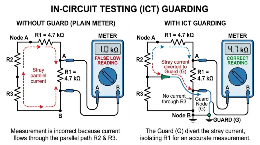
low-side probe, so no current flows through R3 and the tester measures R1 alone.
What a PCB In-Circuit Test Checks
An ICT tester is built to catch manufacturing faults: mistakes made while the board was assembled and soldered. These are the main ones.
| Fault | How the ICT tester finds it | Power |
|---|---|---|
| Solder bridge (short) | Very low resistance between two nets that should be separate | Off |
| Open joint or lifted pin | No connection where the design says there should be one | Off |
| Missing part | OL or a far-off reading at that part’s location | Off |
| Wrong value, such as 1kΩ instead of 10kΩ | Resistance or capacitance outside its tolerance | Off |
| Reversed diode or transistor | The junction reads in the wrong direction | Off |
| Unsoldered IC pin | A sensor plate over the chip checks that each pin is connected | Off |
| Damaged or wrong IC | Digital tests after power-up | On |
| Bad supply voltage | Measures each power rail after power-up | On |
This list matches what The Engineer and I-Connect007 describe for ICT and manufacturing defects analysis. The big advantage is the report. Instead of “board dead,” the technician gets the exact part and the exact reading, so the repair takes minutes.
An ICT tester is not built to prove the whole product works. It checks that the right parts are in the right places and soldered correctly. That is why most factories add a functional test after ICT, which I compare below.
Types of ICT Testers
The term ICT tester covers a few machine types. They all test parts in place, but they reach the board in different ways.
| Type | How it touches the board | Test time per board | Fixture | Best for |
|---|---|---|---|---|
| Bed-of-nails ICT | Hundreds or thousands of fixed pins at once | Usually under a minute | Custom fixture, up to nearly $5,000, up to six weeks to build | High-volume production |
| Flying probe tester | A few moving probes that touch pads one point at a time | Several minutes | None | Prototypes and small batches |
| Manufacturing defects analyzer (MDA) | Bed of nails, simpler electronics | About the same as ICT | Custom fixture | Unpowered checks only: shorts, opens, part values |
| Boundary scan (JTAG) | A few connector pins; the chips test themselves | Varies by board | Little or none | Dense boards with BGA chips that pins cannot reach |
The bed-of-nails and flying probe figures come from I-Connect007’s comparison. The same article puts the per-board test cost under about $1.24 on ICT, compared with $62 or more on a flying probe. A bed-of-nails fixture also needs a test pad on every net, at least 0.050 inch (50 thou) wide.
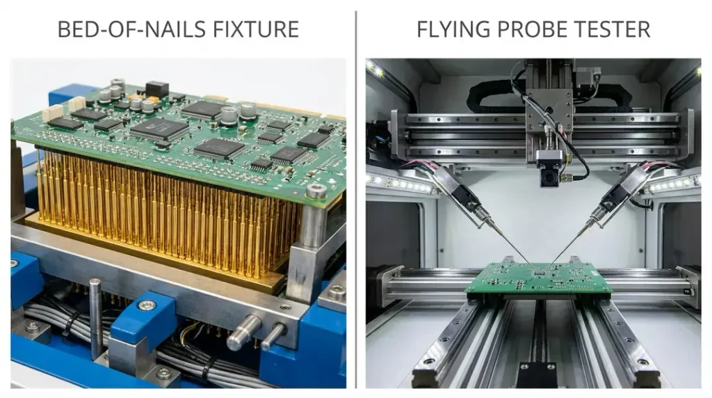
custom fixture for each board. A flying probe needs no fixture but
tests one point at a time, so it suits prototypes and small runs.
Which one fits which job:
- New design or small batch: a flying probe tester. There is no fixture to pay for, and a design change only needs a new program.
- Steady, high-volume production: a bed-of-nails ICT tester. The fixture costs more up front, but each board tests in seconds.
- Dense boards with BGA chips: add boundary scan, because many of those pins have no test point.
ICT vs Functional Test, AOI, and X-Ray
No single test finds everything. Factories usually combine two or three of these methods.
| Method | What it does | Good at finding | Misses |
|---|---|---|---|
| AOI (automated optical inspection) | A camera checks the board | Missing or shifted parts, visible solder bridges | Hidden joints, wrong values that look the same |
| X-ray inspection | Looks through the parts | Hidden solder joints under BGA and QFN chips | Wrong values and electrical faults |
| ICT | Measures each part electrically | Shorts, opens, wrong values, reversed parts | Whether the whole product works |
| Functional test (FCT) | Powers the board and runs it like the finished product | Whether the product actually works | Which part caused the failure |
ICT and functional testing work best as a pair. ICT finds the assembly mistakes fast and names the bad part. The functional test then proves the board does its real job.
Pros and Limits of an ICT Tester
Pros:
- Fast, usually under a minute per board
- Points to the exact faulty part and its reading
- Tests unpowered first, so a shorted board is not damaged
- Low cost per board once the fixture is built
Limits:
- The fixture costs money and takes weeks to build
- Every net needs a test point the pins can reach
- A design change can mean a new fixture, as I-Connect007 notes
- It does not prove the finished product works
Design for Test: Making a Board Easy to Test
If you design boards, a few habits make ICT much easier:
- Put a test pad on every net, at least 0.050 inch wide.
- Keep all test pads on one side of the board. Double-sided fixtures cost much more.
- Keep test pads away from tall parts, so the pins can reach them.
- Use chips with boundary scan where pins cannot reach, such as under BGAs.
Can You Do an In-Circuit Test with a Multimeter?
Not a full one. A multimeter has no guarding and only two probes. But you can copy the most useful parts of a PCB in-circuit test on a single board at your bench.
| ICT test | Multimeter version (power off) | Watch out for |
|---|---|---|
| Shorts | Ohms between each power rail and ground | Big capacitors make the reading start low and climb |
| Opens | Continuity from one end of a trace to the other | You need the schematic to know which points connect |
| Resistor value | Ohms across the resistor in place | Parallel parts make it read low |
| Diode direction | Diode mode in both directions | Parts in parallel can hide a bad diode |
| Capacitor value | Capacitance mode | In-circuit readings are often wrong. Remove one leg for a true value |
Tips that make in-circuit readings more reliable:
- Turn the power off and discharge large capacitors before any ohms test.
- Swap the probes on a resistor and measure again. If the two readings differ, a diode or transistor junction is in parallel with it.
- If a resistor reads lower than its color code, lift one leg and measure it alone. That is how Nuts and Volts describes the traditional fix.
- Compare with a known good board. Measuring the same points on a working board is the closest thing to an ICT test program you can have at home.
For step-by-step board tests, see my guides on how to test a motherboard and PCB with a multimeter, how to test a diode, and how to test a capacitor. To track down a solder bridge on a board, use the rail-to-ground method in how to find a short with a multimeter.
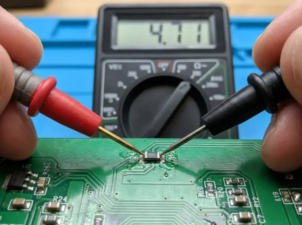
target. A reading well below the marked value usually means a parallel
path, which is what ICT guarding removes.
Real World Example: When the Fixture Pays for Itself
Say a factory builds 2,000 power supply boards a week. It has to choose between a flying probe and a bed-of-nails ICT tester.
Using the I-Connect007 figures, ICT costs about $1.24 per board and flying probe about $62. That is a saving of about $60.76 on every board. A $5,000 fixture is paid off after about 83 boards ($5,000 ÷ $60.76), which is less than one shift.
Now say the line changes a reel of resistors. A few boards later, the ICT tester starts failing boards at one spot: “R14 reads 1.0kΩ, expected 10kΩ.” The operator checks the machine and finds the wrong reel loaded. Without ICT, those boards would reach the functional test with a vague fault such as “output voltage too high,” or worse, ship to customers.
For a run of 20 prototype boards, the math flips. The fixture would cost more than the whole run, and it could take six weeks to build. A flying probe tester is the better choice there.
Common Mistakes with ICT Testing
- Designing a board with no test points. If a pin cannot reach a net, ICT cannot test it.
- Buying a fixture for a prototype run. A flying probe tester is cheaper and faster for small batches.
- Treating an ICT pass as a working product. ICT checks assembly. A functional test proves the board works.
- Ignoring pin contact. Worn or dirty pogo pins cause false failures. Clean and replace them on a schedule.
- Expecting a multimeter to read true values in circuit. Without guarding, parallel parts change the reading. Compare with a good board or lift a leg.
FAQ
What is an ICT tester?
An ICT tester is a machine that checks an assembled circuit board for manufacturing faults. It presses spring-loaded pins onto test points and measures each part in place. It finds shorts, opens, wrong values, reversed parts, and missing parts.
What does ICT stand for in electronics?
ICT stands for in-circuit test. “In-circuit” means each part is measured while it is still soldered on the board. Outside electronics, ICT can also mean information and communication technology.
What is the difference between ICT and a flying probe test?
A bed-of-nails ICT tester touches every test point at once with a custom fixture, so it tests a board in under a minute. A flying probe tester moves a few probes from point to point and needs no fixture, but it takes several minutes per board. ICT suits high volume, and flying probe suits prototypes and small batches.
What is the difference between ICT and functional testing?
ICT checks that every part is correct and soldered properly. A functional test powers the board and checks that it does its real job. Most factories run ICT first, then a functional test.
How long does an in-circuit test take?
A bed-of-nails in-circuit test usually takes less than one minute per board. A flying probe test on the same board can take several minutes.
Can a multimeter do an in-circuit test?
Only a basic one. A multimeter can check for shorts, opens, and diode direction on a board with the power off. It cannot guard out parallel parts, so resistor and capacitor readings in circuit are often wrong.
Conclusion
An ICT tester checks every part on an assembled circuit board in place, usually in less than a minute. Guarding lets it measure one part at a time, even with other parts connected around it.
- Bed-of-nails ICT: fastest and cheapest per board, but it needs a custom fixture and a test point on every net.
- Flying probe: no fixture and quick to set up, but slower per board. Best for prototypes and small batches.
- Boundary scan: tests chips and connections where pins cannot reach.
- Functional test: proves the finished board works, and pairs well with ICT.
At home, a multimeter can copy the basic checks: shorts, opens, and diode direction, with the power off. For true part values, compare with a known good board or lift one leg of the part.
Ready to test a board yourself? My guide on how to test a motherboard, ECU, and PCB with a multimeter walks you through it, step by step.