A resistor might be bad. A wire might have more resistance than it should. A component on a circuit board might have drifted out of spec. All three questions have the same answer: measure the resistance with a multimeter.
This guide covers exactly how to measure resistance with a multimeter, how to read the ohms display correctly, how to test a resistor specifically, and the mistakes that trip up most beginners.
What Is Electrical Resistance?
Electrical resistance is the opposition a material presents to the flow of electric current, measured in ohms (Ω). The higher the resistance, the harder it is for current to flow through that material.
How a Multimeter Measures Resistance
When you select the resistance setting, your multimeter sends a small, known test current through the component you are testing. It measures how much voltage that current produces across the component, then calculates the resistance value using Ohm’s Law. All of this happens instantly, showing up as a single number on the display.
The Ohm Symbol and What It Means
The Ω symbol is the Greek letter Omega, the standard symbol for ohms. Wherever you see this symbol on your multimeter, a component’s datasheet, or a circuit diagram, it refers to resistance.
Finding the Ohms Setting on a Multimeter
What the Resistance Symbol Looks Like
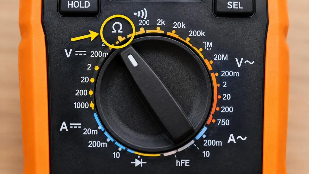
Look for the Ω symbol on your multimeter’s dial. This is the ohms setting on multimeter models across every brand, and it is one of the most consistently placed symbols regardless of manufacturer.
Manual Ranging vs Auto-Ranging for Resistance
An auto-ranging multimeter automatically selects the correct resistance range for you. A manual-ranging multimeter requires you to choose the range yourself, typically options like 200Ω, 2kΩ, 20kΩ, 200kΩ, 2MΩ, and 20MΩ. If you are using a manual meter and are unsure of the expected value, start with a higher range and work your way down until you get a clear, stable reading.
How to Test Resistance with a Multimeter: Step by Step
Step 1: Power Off the Circuit
This is the single most important step. Never measure resistance on a live, powered circuit. The external voltage interferes with the multimeter’s own small test current, producing an inaccurate reading and risking damage to the meter.
Step 2: Set the Dial to the Resistance Setting
Turn the dial to the Ω symbol. On some multimeters, this position shares space with the continuity mode, and a function button switches between the two.
Step 3: Insert the Test Leads
Plug the black lead into the COM port. Plug the red lead into the VΩ port, the same port used for voltage measurement.
Step 4: Disconnect the Component from the Circuit
Remove the component you want to test from the circuit entirely, or at minimum disconnect one leg. Other components still connected in parallel create alternate paths for the multimeter’s test current, which skews your reading and makes it unreliable.
Step 5: Connect the Probes
Touch one probe to each end of the component. Polarity does not matter here, a resistor has no positive or negative side, so it does not matter which probe touches which end.
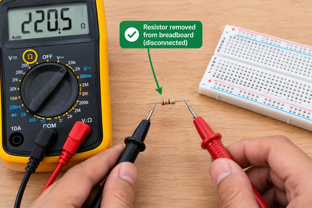
📷 IMAGE RECOMMENDATION 2 Where: Inside Step 5 What: A photo of multimeter probes connected to a resistor that has been removed from a breadboard Alt text: “Multimeter probes connected to a resistor removed from breadboard for accurate resistance measurement” Why: Shows readers exactly what an isolated, correctly disconnected component looks like before testing, reinforcing the disconnection step visually.
Step 6: Read the Display
The number shown is your resistance reading, displayed in Ω, kΩ, or MΩ depending on the value and your multimeter’s auto-ranging behavior.
How to Read Ohms on a Multimeter
Understanding Ω, kΩ, and MΩ
| Unit | What It Means |
|---|---|
| Ω | Ohms, used for small resistance values |
| kΩ | Kilohms, equal to 1,000 ohms |
| MΩ | Megohms, equal to 1,000,000 ohms |
What a Normal Resistance Reading Looks Like
A healthy component reads close to its rated value, with some acceptable variation. Most standard resistors carry a manufacturing tolerance of 5% or 10%, so a small difference between the printed value and your measured reading is completely normal, not a sign of failure.
What Does OL Mean During a Resistance Test
OL means overload. This tells you the resistance is higher than your currently selected range can display. It can mean two different things: either you need to switch to a higher range on a manual-ranging meter, or the component genuinely has an open circuit and has failed internally.
How to Test a Resistor with a Multimeter
Why a Resistor Must Be Removed from the Circuit First
Testing a resistor while it remains wired into a larger circuit almost always gives you an inaccurate reading. Other resistors, capacitors, or components connected around it create parallel paths, and your multimeter measures the combined resistance of all of them together, not the single component you actually care about.
Comparing Your Reading to the Resistor’s Rated Value
Once isolated, touch a probe to each end of the resistor and read the display. Compare this number to the resistor’s printed or rated value.
Resistor Color Code vs Multimeter Reading
Resistors use colored bands to indicate their rated value and tolerance, a system that works well until the bands are faded, dirty, or difficult to read confidently. A multimeter reading gives you a direct, unambiguous confirmation of the actual value, and it also catches a resistor that has drifted out of spec over time even though its color bands still show the original rated value.
Resistor Test Results Table
| Reading | What It Means |
|---|---|
| Within the resistor’s stated tolerance | Resistor is good |
| Significantly higher than rated value | Resistor has drifted or is failing |
| OL displayed | Resistor is open circuit, replace it |
| Reading close to 0Ω | Resistor is shorted, replace it |
Example: A resistor marked 220Ω with 5% tolerance should read somewhere between roughly 209Ω and 231Ω. A reading of 218Ω is perfectly normal. A reading of OL or 0Ω means the resistor has failed.
Using Alligator Clips for Hands-Free Resistance Testing
Why Alligator Clips Help
Instead of manually holding the probes against a small component, alligator clips let you connect the multimeter leads directly to the component and let go. This gives you a more stable connection and frees both hands, especially useful when testing something small on a breadboard or when you need to watch a reading over a period of time.
📷 IMAGE RECOMMENDATION 3 Where: Below this section heading What: A photo of alligator clip leads connected to a resistor with the multimeter display visible in the background Alt text: “Alligator clip leads connected to a resistor for hands free resistance testing” Why: Alligator clip testing is a genuinely useful technique many beginners have never seen demonstrated, and a photo makes the setup immediately clear.
How to Set Up Alligator Clip Leads
- Attach one alligator clip lead to your multimeter’s red probe tip
- Attach the other alligator clip lead to the black probe tip
- Clip the opposite ends of each lead onto the two ends of the component you are testing
- Read the display exactly as you would with standard probes
How to Know If Your Multimeter Is Working Properly
Testing Your Meter Against a Known Resistor
Before trusting an unexpected reading, verify your multimeter itself is functioning correctly. Test it against a resistor with a clearly known, printed value. If the reading closely matches what you expect, your multimeter is working properly and you can trust the next reading you take.
Touching the Probes Together as a Quick Check
Touch the red and black probe tips together while in resistance mode. You should see a reading very close to 0Ω. If the display shows something unexpected, check your leads, your battery, and your dial setting before assuming a component you test afterward is actually faulty.
Common Mistakes When Testing Resistance
Measuring Resistance on a Live Circuit
Always power down the circuit completely before switching to resistance mode. Voltage from a live circuit interferes with the multimeter’s own test current and can permanently damage the meter.
Testing a Component Still Connected to the Circuit
As covered above, leaving a component wired into a larger circuit introduces parallel paths that skew your reading. Always disconnect at least one leg before testing.
Holding the Component While Measuring
Your body has its own resistance, and holding a component with your fingers while probing it, especially at high resistance values in the megohm range, can introduce enough interference to affect the reading. Hold the component by an insulated section, or better yet, use alligator clips instead.
Using the Wrong Range
On a manual-ranging multimeter, selecting a range too low for the actual resistance value gives you an OL reading even though the component is perfectly fine. Selecting a range too high can make small differences harder to read precisely. Start high and work your way down if you are unsure of the expected value.
FAQ
How do you check ohms on a multimeter?
Turn the dial to the Ω symbol, plug the black lead into COM and the red lead into the VΩ port, then touch one probe to each end of the component you want to test, after first disconnecting it from any powered circuit. The resistance value appears on the display in ohms, kilohms, or megohms.
Why do I need to disconnect a component before measuring resistance?
Other components still connected in the same circuit create parallel paths for the multimeter’s test current, which skews the reading and makes it unreliable. Disconnecting the component, or at least one of its legs, isolates it so your reading reflects that single component’s true resistance value.
What does OL mean when measuring resistance?
OL means overload, indicating the resistance is higher than the range your multimeter is currently set to measure. On a manual-ranging meter, switch to a higher range and try again. If the reading still shows OL at the highest available range, the component likely has an open circuit and has failed.
Can I use a multimeter to check resistors in a circuit?
You can attempt it, but for an accurate reading you should first disconnect the resistor from the circuit, or at least one of its leads. Testing while it remains fully connected risks an inaccurate reading, since other nearby components create alternate current paths that interfere with the measurement.
Is it okay to hold a component while measuring resistance?
It is generally fine for low resistance values, but your body’s own resistance can interfere with readings at very high resistance, particularly in the megohm range. For the most accurate results, hold the component by an insulated section if possible, or use alligator clip leads to avoid direct contact entirely.
Can a multimeter also check battery voltage?
Yes. Set the dial to DC voltage instead of resistance, place the red probe on the battery’s positive terminal and the black probe on the negative terminal, and read the voltage on the display. This is a completely separate measurement from resistance testing, using a different dial setting.
Conclusion
Measuring resistance with a multimeter comes down to a simple sequence: power off the circuit, set the dial to Ω, disconnect the component you are testing, and read the display.
A normal reading falls within the component’s stated tolerance. OL means either you need a higher range or the component has failed open. A reading near 0Ω on something that should show real resistance usually points to a short. And always verify your multimeter itself is working correctly against a known resistor before trusting an unusual result on something new.
2 thoughts on “How to Measure Resistance with a Multimeter (Complete Guide)”