You plugged in your device and nothing happened. You replaced the fuse and it still does not work. You suspect a broken wire somewhere — but which one?
A continuity test with a multimeter answers that question in seconds. One beep and the wire is good. Silence means it is broken.
This guide teaches you exactly how to test continuity with a multimeter, what the beep means, what to do when there is no beep, and how to test resistance too. Every step is explained in plain language for complete beginners.
What Is Continuity?
Continuity means there is a complete unbroken electrical path between two points that allows current to flow freely.
Think of it like a garden hose. If the hose is intact water flows from one end to the other. That is continuity. If there is a crack or hole in the hose the water cannot get through. That is an open circuit with no continuity.
In electrical terms a wire has continuity when the copper inside is intact and unbroken. A fuse has continuity when the internal wire has not melted. A switch has continuity when the contacts are closed and touching.
Why Does Continuity Testing Matter?
Wires can look perfect on the outside while being broken internally. A fuse looks intact but may have blown. A switch feels like it clicks but the internal contacts have burned out.
Visual inspection misses all of these failures. A continuity test catches them instantly.
Use continuity testing to:
- Find broken wires inside extension cords and appliance cables
- Check if a fuse has blown
- Verify a switch opens and closes correctly
- Trace which wire goes where in a bundle of identical cables
- Check if two points are connected that should not be (short circuit check)
- Verify solder joints and PCB traces on circuit boards
What Does the Continuity Symbol Look Like on a Multimeter?
The continuity symbol on a multimeter looks like a small sound wave or speaker icon. It is usually three small arcs radiating outward — similar to a Wi-Fi signal symbol or sound coming from a speaker.
On many multimeters, the continuity symbol shares a position on the dial with the diode test symbol. The diode symbol looks like a triangle pointing toward a vertical line with a small horizontal line through it.
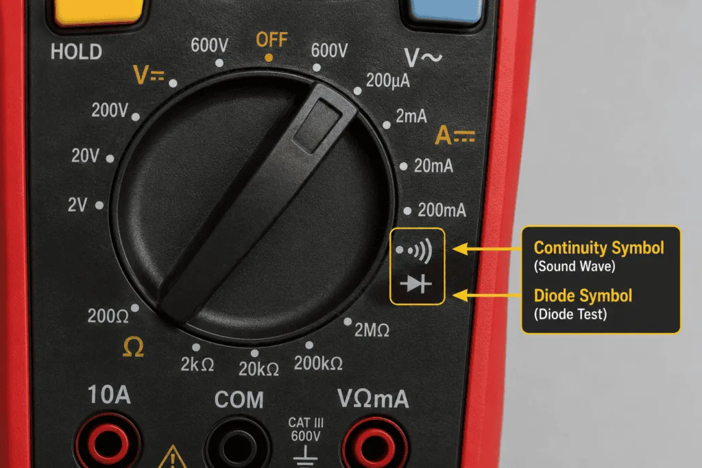
Look for one of these on your multimeter dial:
| Symbol | What It Looks Like | What It Means |
|---|---|---|
| ))) | Three small arcs like a Wi-Fi signal | Continuity mode |
| → | Triangle pointing to a vertical line | |
| CONT | The word CONT | Continuity mode on some models |
If your multimeter does not have a continuity symbol, it may not have a dedicated continuity mode. In this case, use the resistance (Ω) setting instead — see the resistance testing section below.
How to Set Up Your Multimeter for Continuity Testing
Setting up for a continuity test takes less than 30 seconds. Here is exactly what to do.
Step-by-Step Multimeter Setup
- Plug the black probe into the COM port
- Plug the red probe into the VΩ port (the same port used for voltage and resistance)
- Turn the dial to the continuity symbol (sound wave or three arcs)
- On some multimeters, you need to press a function button to switch from diode mode to continuity mode — check your manual if the meter does not beep in the next step
- Touch the two probe tips together — you should hear a beep immediately
If you hear a beep when touching the probes together, your multimeter is set up correctly and is ready to use.
If you do not hear a beep, check that the dial is fully clicked into the correct position and that both probes are firmly inserted into their ports.
💡 Tip: Not sure what the symbols on your multimeter dial mean? Check out our Multimeter Symbols Guide for a complete reference of every setting.
How to Test Continuity with a Multimeter: Step by Step
Now that your multimeter is set up, here is how to run a continuity test on any wire, fuse, switch, or component.
Step 1: Turn Off the Power
⚠️ Warning: Always turn off power to the circuit before testing continuity. Testing a live circuit gives false readings and can damage your multimeter. Turn off the circuit breaker or unplug the device completely.
Step 2: Isolate the Component
Disconnect the wire, fuse, switch, or component from the circuit at least at one end. Other components connected in parallel can create false continuity readings even when the component you are testing is actually broken.
Step 3: Touch the Probes to Each End
Touch one probe to each end of the wire, fuse, or component you want to test. It does not matter which probe goes on which end for continuity testing; polarity is not important.
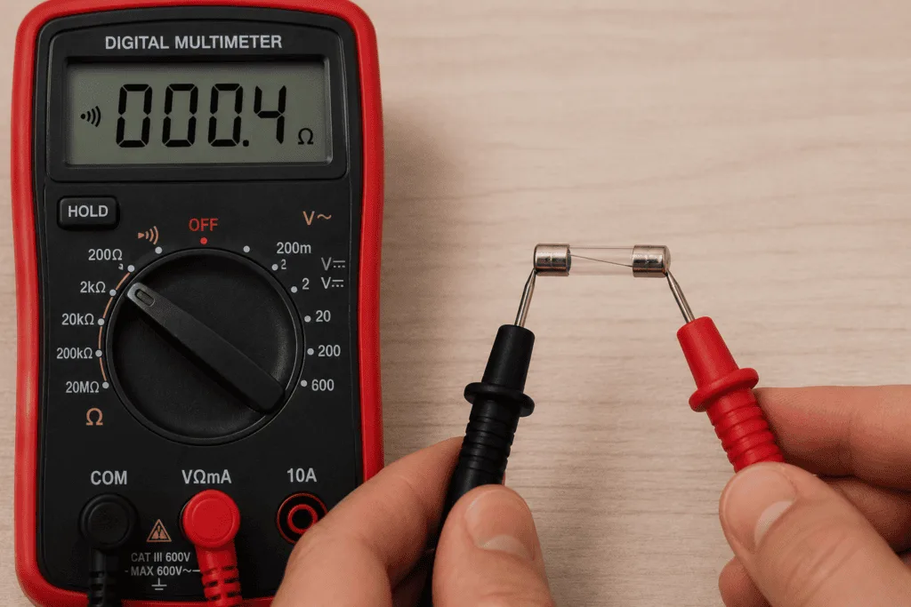
Step 4: Listen and Read the Display
Listen for the beep and watch the display.
Step 5: Record the Result
Write down your result and compare it to the table below.
What Does the Beep Mean on a Multimeter?
The beep tells you that your multimeter detected very low resistance between the two probe points — meaning electricity can flow freely between them.
Most multimeters beep when the resistance is below 20 to 40 ohms. This threshold varies between multimeter models. At higher resistance levels, the beep stops even if some current can still flow.
Continuity Test Results Table
| Result | Display Shows | What It Means | What to Do |
|---|---|---|---|
| Continuous beep | 0.0 to low Ω | Complete circuit — continuity confirmed | Component is good |
| No beep | OL | Open circuit — path is broken | Replace the wire or component |
| Short beep then silence | OL after beep | Capacitor charging — normal behavior | Wait and retest |
| Beep only sometimes | Fluctuating | Intermittent fault — loose connection | Inspect connections carefully |
What If I Hear a Short Beep and Then Silence?
This confuses many beginners, and it is completely normal.
When you test continuity near capacitors, you may hear a quick beep followed by silence. This is because capacitors briefly act like a short circuit when they first receive current. They charge up in a split second and then block current like an open circuit.
So you hear a beep as the capacitor charges and then silence as it reaches full charge. This is normal. The capacitor is working correctly. If you were checking a wire or fuse near a capacitor, this short beep does not mean the wire is broken.
Real World Continuity Testing Examples
Testing a Fuse
Set your multimeter to continuity mode. Touch one probe to each metal end of the fuse. A beep means the fuse is good — current can flow through it. No beep means the fuse has blown and needs replacing.
This is faster and more reliable than visual inspection. A blown fuse often looks perfectly intact on the outside.
Testing an Extension Cord
Unplug the extension cord from the wall. Touch one probe to the live pin on the plug end. Run the other probe to the matching socket at the other end. A beep confirms that wire is intact. Repeat for the neutral and ground wires. No beep on any wire means that conductor is broken inside the cord.
Testing a Switch
Touch one probe to each terminal of the switch. Flip the switch to the ON position. You should hear a beep — the contacts are closed and electricity can flow. Flip to OFF — the beep should stop. If the switch beeps in both positions the contacts are stuck closed. If it never beeps the contacts have failed open.
Testing Wires in a Harness
When you have a bundle of identical wires and need to identify which wire goes where use the continuity test. Connect one probe to the wire at one end of the harness. Have a helper touch the other probe to each wire at the other end until the meter beeps. The wire that beeps is the one connected to your probe.
Common Continuity Testing Mistakes Beginners Make
Testing a Live Circuit
The most common mistake. Continuity mode sends its own tiny current through the circuit. If the circuit is live the external voltage interferes with the reading and gives false results. Always turn off power first.
Not Pressing the Probes Firmly Enough
Loose probe contact gives an open circuit reading even on a good component. Press the probe tips firmly against the metal contact point. Touching insulation instead of bare metal gives no reading at all.
Misreading the Capacitor Beep
As explained above, a short beep followed by silence is normal when testing near capacitors. Many beginners think the short beep means the component is good, then second-guess themselves when it goes silent. The short beep is just the capacitor charging — wait a moment, and if silence follows, the component being tested is open circuit.
Using Continuity Mode on a Live Circuit for Diode Testing
Continuity mode and diode test mode are different. For testing diodes, use diode test mode — not continuity mode. Diode test mode shows you the forward voltage drop. Continuity mode just tells you if current can flow, which gives you less information about diode health.
Forgetting to Test the Multimeter First
Always touch the probes together before testing anything. If you do not hear a beep, the battery may be low, the probes may be faulty, or the dial may not be fully clicked into the continuity position. Confirm the self-test beeps before trusting any test result.
How to Test Resistance with a Multimeter (Ohms)
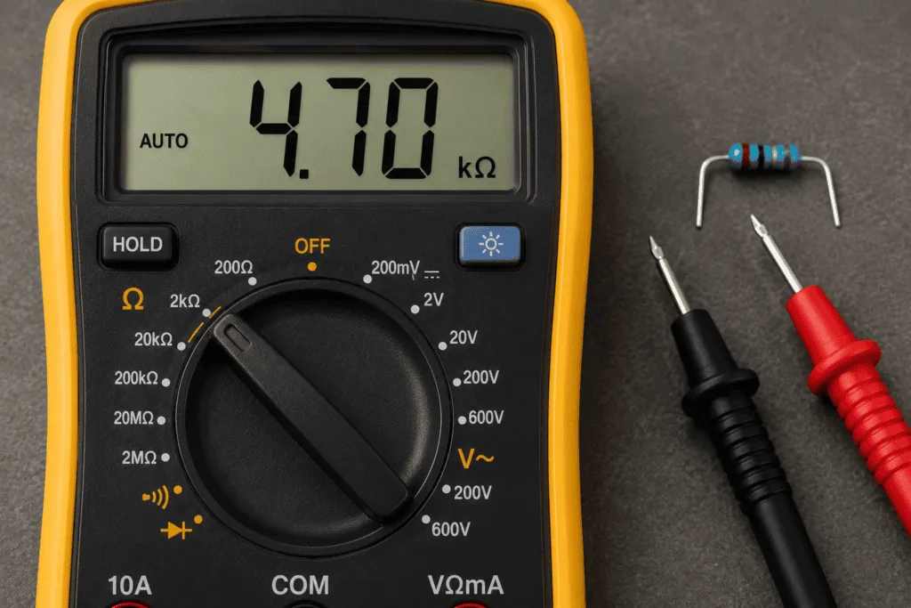
Resistance testing goes one step further than continuity testing. Instead of just telling you if a circuit is complete, it tells you exactly how much resistance is in the circuit, measured in ohms (Ω).
When to Use Resistance Mode Instead of Continuity Mode
Use continuity mode for a quick pass or fail check — beep means good, silence means broken.
Use resistance mode when you need to know the exact resistance value — for example when checking a heating element, a motor winding, or a specific resistor.
How to Set Your Multimeter to Ohms
- Keep the probes plugged into the same ports (black in COM, red in VΩ)
- Turn the dial to the Ω symbol
- If your multimeter is not auto-ranging start at the highest range and work down
- Touch the probes to the component you want to test
How to Read Ohm Values on a Multimeter
The display shows a number followed by a unit:
| Display | Meaning |
|---|---|
| Ω | Ohms — for small resistance values |
| kΩ | Kilohms — 1,000 ohms |
| MΩ | Megohms — 1,000,000 ohms |
| OL | Open loop — resistance is too high to measure or circuit is broken |
| 0.0 Ω | Very low resistance — close to a short circuit |
What Is a Good Resistance Reading?
The answer depends entirely on what you are testing. Here are common reference values:
| Component | Expected Resistance | Bad Reading |
|---|---|---|
| Good wire or connection | 0Ω to a few Ω | OL |
| Blown fuse | OL | Should be near 0Ω |
| Good fuse | Close to 0Ω | OL |
| Open switch | OL | Depends on switch type |
| Closed switch | Close to 0Ω | OL |
| Broken wire | OL | Should be near 0Ω |
| Dryer heating element | 5Ω to 50Ω | OL means burned out |
| 1kΩ resistor | 950Ω to 1050Ω | Very different reading means failed |
What Does OL Mean on a Multimeter During Resistance Testing?
OL means open loop. The resistance is higher than your selected range can measure. This happens when:
- The component has an open circuit (broken wire, blown fuse, failed component)
- You selected a range that is too low — switch to a higher range
- The probes are not making good contact — press more firmly
OL during resistance testing on a component that should have low resistance (like a wire or fuse) means the component has failed and needs replacing.
Continuity vs Resistance: Which Should You Use?
| Situation | Best Test | Why |
|---|---|---|
| Quick pass or fail check on a wire | Continuity | Faster — just listen for the beep |
| Checking a fuse | Continuity | Instant result |
| Testing a switch | Continuity | Easy to hear the click and beep together |
| Checking a heating element | Resistance | Need to know the exact ohm value |
| Testing a motor winding | Resistance | Need to compare to spec |
| Identifying a specific wire in a bundle | Continuity | Quick and hands-free |
| Checking a resistor value | Resistance | Need the exact number |
💡 Tip: For more complete wire testing including coax cable, Ethernet, and phone lines check out our Testing Wires Guide.
FAQ
What does continuity mean on a multimeter?
Continuity on a multimeter means there is a complete unbroken electrical path between the two probe points. When continuity is detected the multimeter beeps. No beep means the path is broken — an open circuit. Use continuity mode to check wires, fuses, switches, and connections.
How do I set my multimeter to continuity mode?
Plug the black probe into COM and the red probe into the VΩ port. Turn the dial to the continuity symbol — it looks like a small sound wave or three arcs. Touch the two probe tips together. If you hear a beep the meter is in continuity mode and ready to use. On some multimeters, you need to press a function button to switch from diode mode to continuity mode.
What does OL mean during a continuity test?
OL means open loop — there is no complete path between the two probe points. During a continuity test OL means the wire or component is broken or disconnected. Replace the faulty component. OL is the bad result in continuity testing.
Why did I hear a short beep and then silence?
A short beep followed by silence usually means there is a capacitor in the circuit near where you are testing. Capacitors briefly act like a short circuit when they first receive current causing the meter to beep. Then they charge up and block current causing the beep to stop. This is normal behavior — the capacitor is working correctly.
Can I test continuity on a live circuit?
No. Always turn off power before testing continuity. Testing a live circuit gives false readings because the external voltage interferes with the small current the multimeter uses for continuity testing. In some cases it can also damage the multimeter. Always unplug or switch off the circuit breaker first.
What is the difference between continuity and resistance testing?
Continuity testing gives you a simple yes or no answer with a beep. Either there is a complete path or there is not. Resistance testing gives you a specific number in ohms telling you exactly how much the circuit resists current flow. For quick checks use continuity. For exact measurements use resistance mode.
Conclusion
Testing continuity with a multimeter is one of the most useful skills you can learn for electrical troubleshooting.
Turn off the power. Set the dial to the continuity symbol. Touch the probes to each end of the component. Listen for the beep.
A beep means the circuit is complete and the component is intact. No beep means it is broken and needs replacing.
For more precise testing use resistance mode to measure the exact ohm value. Compare your reading to the expected value for the component — a significant difference or an OL reading means the component has failed.
Always confirm the meter beeps when you touch the probes together before testing anything. A meter that does not self-test is not ready to use.
1 thought on “How to Test Continuity with a Multimeter (+ Resistance)”