Your HVAC system is reading the wrong temperature. Your industrial process controller shows an error. Your furnace sensor seems disconnected from reality.
The problem is often a failed temperature sensor — and a multimeter is the fastest way to confirm it. This guide shows you exactly how to test a PT100, a 3-wire or 4-wire RTD, and NTC or PTC thermistors, with a complete resistance-temperature reference table so you know exactly what a good reading looks like.
What Is a PT100 Sensor?
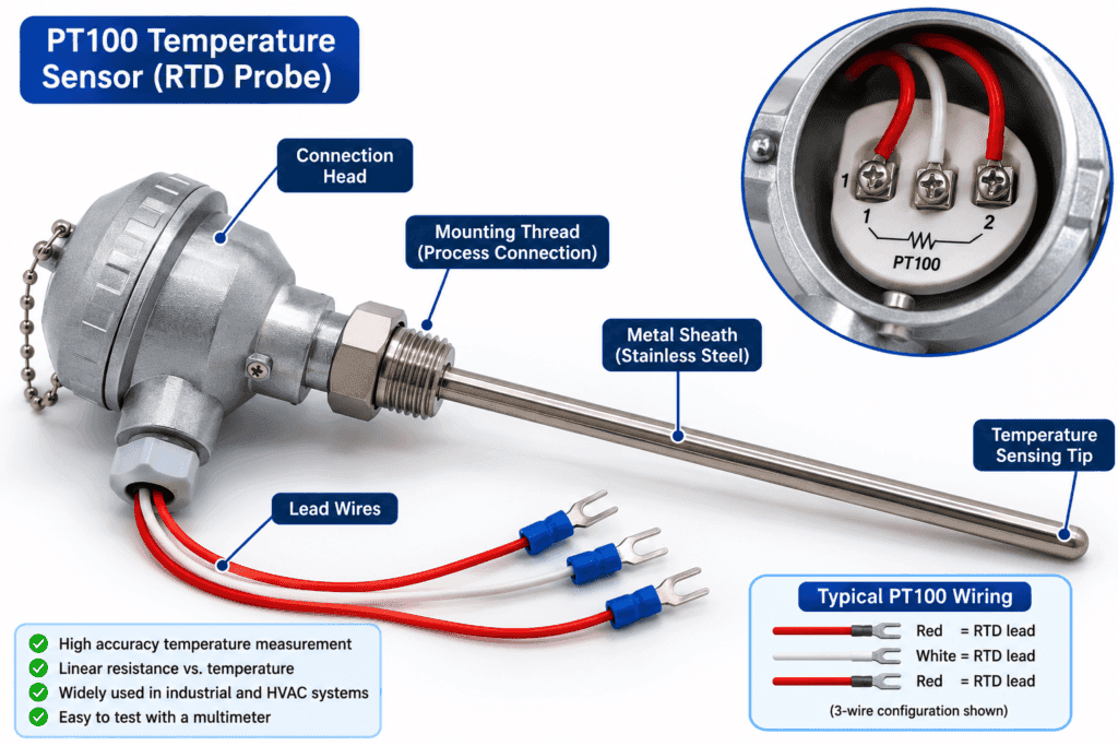
A PT100 is a Resistance Temperature Detector (RTD) made from a thin platinum wire whose electrical resistance changes predictably as temperature changes. The “100” in PT100 means the sensor reads exactly 100 ohms at 0°C.
As temperature rises the resistance of the platinum wire rises too — in a nearly linear, predictable way. By measuring the resistance with a multimeter, you can work out the approximate temperature the sensor is exposed to.
How Does a PT100 Sensor Work?
Platinum is used because it is a stable, inert metal that resists corrosion and produces a very consistent, repeatable change in resistance with temperature. The most common PT100 type changes resistance at a rate of approximately 0.385 ohms for every 1°C rise in temperature. This is known as the alpha coefficient, and this sensor type is often called the “PT100 (385).”
What Does the “100” in PT100 Mean?
The number 100 refers to the sensor’s resistance in ohms at 0°C. A PT100 reads 100Ω at freezing point. A related sensor called PT1000 reads 1000Ω at 0°C — the same working principle but ten times the resistance, giving better noise immunity in long cable runs.
Where Are PT100 Sensors Used?
PT100 sensors are used anywhere precise, stable temperature measurement matters:
- HVAC systems and building automation
- Industrial process control (chemical, food, pharmaceutical)
- Laboratory and calibration equipment
- Refrigeration and cold chain monitoring
- Motor and transformer winding temperature monitoring
What You Need Before You Start
Tools Required
- A digital multimeter with resistance mode (Ω), ideally with a low range around 0-200Ω
- Red and black test leads
- A thermometer to note the ambient temperature during testing (optional but helpful)
How to Set Up Your Multimeter for PT100 Testing
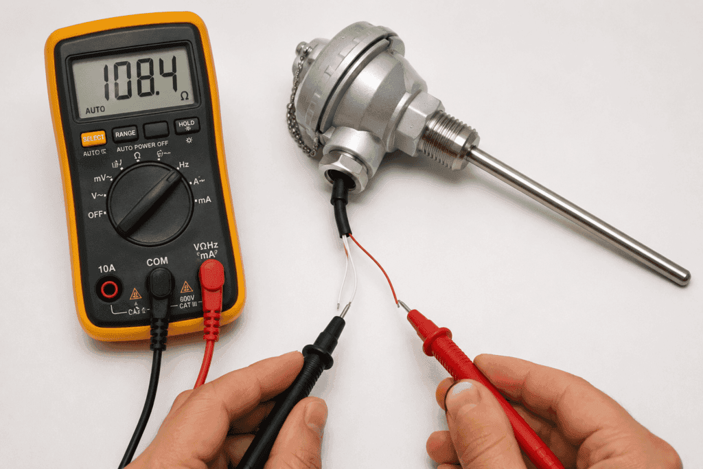
- Plug the black probe into the COM port
- Plug the red probe into the VΩ port
- Turn the dial to resistance mode (Ω)
- If your multimeter is manual-ranging, select the lowest range that covers 100Ω to 150Ω — usually the 200Ω range
- Touch the probe tips together to check the lead resistance and subtract this small value from your final reading if high accuracy is needed
Testing PT100 Resistance with a Multimeter
Step 1: Disconnect the Sensor
Disconnect the PT100 from its controller, transmitter, or I/O card before testing. Testing while still wired into the system can give false readings caused by other components in the circuit.
Step 2: Set the Multimeter to Resistance Mode
Turn the dial to Ω and select the low range (0-200Ω) if your meter is not auto-ranging. PT100 sensors have a small resistance range so a low range gives you the most accurate reading.
Step 3: Identify the Wire Configuration
PT100 sensors come with 2, 3, or 4 lead wires. Identify which type you have before connecting the probes — see the dedicated 3-wire and 4-wire sections below for details.
Step 4: Connect the Probes and Read the Resistance
Touch one probe to each of the two measurement wires. Polarity does not matter for resistance measurement. Wait a moment for the reading to stabilize.
Step 5: Compare to the Expected Value
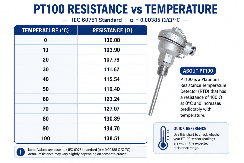
Note the current ambient temperature of the sensor if possible, then compare your reading to the resistance-temperature table below.
Reading PT100 Values: Resistance-Temperature Table
PT100 Resistance-Temperature Chart
| Temperature (°C) | Expected Resistance (Ω) |
|---|---|
| -20°C | 92.16Ω |
| -10°C | 96.09Ω |
| 0°C | 100.00Ω |
| 10°C | 103.90Ω |
| 20°C | 107.79Ω |
| 25°C (room temp) | 109.73Ω |
| 30°C | 111.67Ω |
| 40°C | 115.54Ω |
| 50°C | 119.40Ω |
| 60°C | 123.24Ω |
| 70°C | 127.07Ω |
| 80°C | 130.89Ω |
| 90°C | 134.70Ω |
| 100°C | 138.50Ω |
💡 Tip: These values apply to the standard PT100 (385) sensor used in most HVAC and general industrial applications. If your sensor is a different alpha type (such as PT100 391) check the manufacturer datasheet for its specific resistance-temperature table.
What a Good Reading Looks Like
A good PT100 reads a resistance value close to the expected value in the table above, based on the sensor’s current ambient temperature. At room temperature (around 25°C) a healthy PT100 reads approximately 109.7Ω.
What a Bad Reading Looks Like (Open or Short Circuit)
| Result | What It Means |
|---|---|
| OL (open loop) | Open circuit — broken wire or internal sensor failure |
| 0Ω or near zero | Short circuit — internal fault or shorted wiring |
| Reading does not change with temperature | Sensor element has failed internally |
| Reading significantly off the table value | Sensor drift — recalibrate or replace |
What Does OL Mean on a PT100 Test?
OL means open loop — there is no complete electrical path through the sensor. This usually means a broken internal platinum wire or a snapped lead wire. A PT100 reading OL cannot be repaired and needs replacing.
Testing a 3-Wire RTD with a Multimeter
Why 3-Wire RTDs Are Different from 2-Wire
A 2-wire RTD is simple, but the resistance of the lead wires themselves gets added to the measurement, causing inaccuracy over long cable runs. A 3-wire RTD adds a third lead specifically to measure and cancel out this lead wire resistance, giving a much more accurate reading. This is the most common RTD configuration used in industry.
How to Identify the Three Wires
A 3-wire RTD has two wires that read the same resistance to each other (these are connected to the same sensor terminal internally) and one wire that reads differently. Use these steps to identify them:
- Test resistance between all three possible wire pairs
- Two of the three combinations will show a similar higher resistance value (close to the sensor’s expected value)
- One combination will show a very low resistance (close to 0Ω) — these are your two identical wires
- The wire not involved in that low-resistance pair is the different lead
Step-by-Step 3-Wire RTD Test
- Disconnect the RTD from the circuit
- Set your multimeter to resistance mode (Ω)
- Test each pair of wires (there are three possible pairs)
- Identify the pair of identical wires (low resistance between them, close to 0Ω — this is the lead wire resistance)
- Measure between one identical wire and the different wire — this reading is closest to the true sensor resistance plus one lead resistance
- Compare this reading to the resistance-temperature table, allowing a small offset for the single lead resistance
3-Wire RTD Results Table
| Test | Expected Result | What It Means |
|---|---|---|
| Between the two identical wires | Very low (0.5Ω to a few Ω) | Normal lead wire resistance |
| Between identical wire and different wire | Close to table value plus small offset | Sensor is working |
| OL on any pair | Open circuit | Sensor or lead wire is broken |
| 0Ω on the sensor-element pair | Short circuit | Sensor has failed |
Testing a 4-Wire RTD with a Multimeter
Why 4-Wire RTDs Are the Most Accurate
A 4-wire RTD uses two wires to carry the small test current through the sensor and two completely separate wires to measure the voltage drop across the sensor element. This design completely eliminates lead wire resistance from the measurement, giving the highest possible accuracy. It is used in laboratory and high-precision industrial applications.
Step-by-Step 4-Wire RTD Test
- Disconnect the RTD from the circuit
- Set your multimeter to resistance mode (Ω)
- Identify the two pairs — current-carrying wires and voltage-sensing wires (check the sensor datasheet as this varies by manufacturer)
- Measure across the voltage-sensing pair for the most accurate reading
- Compare to the resistance-temperature table — this reading requires no offset correction
💡 Tip: A standard multimeter cannot perform true 4-wire (Kelvin) measurement the way a precision bench meter can, but measuring across the sense wire pair still gives you an accurate resistance reading close to the sensor’s true value.
Testing NTC/PTC Thermistors with a Multimeter
What Is a Thermistor?
A thermistor is a temperature sensor made from a semiconductor material rather than platinum wire. Unlike a PT100, a thermistor’s resistance changes dramatically with temperature — often by hundreds or thousands of ohms per degree — making it very sensitive but less linear than an RTD.
NTC vs PTC: What Is the Difference?
NTC (Negative Temperature Coefficient): Resistance decreases as temperature increases. This is the most common thermistor type, used in appliances, HVAC systems, and automotive temperature sensors.
PTC (Positive Temperature Coefficient): Resistance increases as temperature increases. Used for overcurrent protection, motor winding protection, and some specialized heating applications.
Step by Step Thermistor Test
- Disconnect the thermistor from the circuit
- Set your multimeter to resistance mode (Ω) — thermistors often need a higher range than PT100 sensors (kΩ range is common)
- Touch one probe to each thermistor lead
- Note the resistance and the current ambient temperature
- Compare to the thermistor’s datasheet resistance-temperature table (values vary significantly by part number, unlike the standardized PT100 table)
- For a quick functional check, gently warm the thermistor (with your fingers or warm air) while watching the reading

Thermistor Test Results Table
| Result | NTC Thermistor | PTC Thermistor |
|---|---|---|
| Resistance drops when warmed | Normal — sensor is working | Sensor may be faulty (should rise) |
| Resistance rises when warmed | Sensor may be faulty (should drop) | Normal — sensor is working |
| OL at any temperature | Open circuit — replace sensor | Open circuit — replace sensor |
| 0Ω or near zero | Shorted — replace sensor | Shorted — replace sensor |
| No change at all when warmed | Sensor element has failed | Sensor element has failed |
PT100 vs Thermocouple vs Thermistor
Comparison Table
| Feature | PT100 (RTD) | Thermocouple | Thermistor |
|---|---|---|---|
| Sensing element | Platinum wire | Two dissimilar metals | Semiconductor |
| Output signal | Resistance change | Small voltage (mV) | Resistance change |
| Accuracy | Very high | Moderate | High but narrow range |
| Linearity | Nearly linear | Non-linear | Highly non-linear |
| Temperature range | -200°C to 850°C | -200°C to 1800°C+ | -50°C to 150°C typical |
| Response time | Moderate | Fast | Fast |
| Cost | Moderate to high | Low | Low |
| Testing with multimeter | Resistance mode | DC millivolt mode | Resistance mode |
Which Sensor Type Should You Use?
Choose a PT100 for high accuracy, stable long-term readings, and moderate temperature ranges — the standard choice for HVAC and process control.
Choose a thermocouple for very high or very low extreme temperatures and fast response time — common in furnaces, kilns, and exhaust systems.
Choose a thermistor for low-cost, highly sensitive measurement over a narrow temperature range — common in appliances and consumer electronics.
Common PT100 Testing Mistakes
Testing While Still Connected to the Circuit
Other components wired in parallel with the sensor create false low readings. Always disconnect at least one lead before testing.
Using the Wrong Resistance Range
PT100 sensors operate in a narrow 80Ω to 150Ω range for most everyday temperatures. Using a high range setting (like 20kΩ) on a manual-ranging multimeter reduces reading precision. Always select the lowest range that comfortably covers the expected value.
Ignoring Lead Wire Resistance
On a 2-wire RTD with long cable runs the wire itself can add several ohms of resistance, making the sensor appear warmer than it actually is. For critical measurements, always account for lead resistance or use a 3-wire or 4-wire configuration.
Testing in an Uncontrolled Environment
Drafts, direct sunlight, or nearby heat sources can change the sensor’s actual temperature during testing, making your reading harder to compare against the table. Test in a stable, controlled environment whenever possible for the most reliable comparison.
FAQ
What should a PT100 read on a multimeter at room temperature?
At a typical room temperature of 25°C, a healthy PT100 sensor reads approximately 109.73Ω. At exactly 0°C it reads 100.00Ω. Use the full resistance-temperature table in this guide to compare your reading to the sensor’s actual ambient temperature at the time of testing.
How do I check a 3-wire RTD with a multimeter?
Test resistance between all three possible wire pairs. Two wires will show a very low resistance between them (close to 0Ω) — these are the identical lead wires. Measure between one of these and the third, different wire. This reading represents the sensor resistance plus one lead wire resistance, and should be close to the expected value in the resistance-temperature table.
What does OL mean when testing a PT100?
OL means open loop — there is no complete electrical path through the sensor. This indicates a broken lead wire or an internal failure of the platinum sensing element. A PT100 reading OL has failed and needs to be replaced, since these sensors are not repairable.
How do I test a thermistor with a multimeter?
Set your multimeter to resistance mode, often in the kΩ range since thermistors typically have higher resistance than PT100 sensors. Touch the probes to the two leads and note the reading along with the current temperature. For an NTC thermistor the resistance should drop when warmed. For a PTC thermistor, the resistance should rise when warmed. No change indicates a failed sensor.
What is the difference between PT100 and PT1000?
The primary difference is the resistance at 0°C. A PT100 reads 100 ohms at 0°C while a PT1000 reads 1000 ohms at 0°C. PT1000 sensors are increasingly popular in longer cable runs because their higher resistance makes lead wire resistance and electrical noise proportionally less significant, improving measurement accuracy without needing a 3-wire or 4-wire configuration.
Can a faulty PT100 sensor be repaired?
No. PT100 sensors are sealed, precision-manufactured devices. Once the internal platinum element or lead wire has failed, repair is not practical or cost-effective. If your multimeter test shows OL, a short circuit, or a reading significantly off the expected resistance-temperature table value, the sensor needs to be replaced.
Conclusion
Testing a PT100, RTD, or thermistor with a multimeter is a fast, reliable way to confirm whether a temperature sensor is working correctly before you replace expensive equipment or call a technician.
Disconnect the sensor, set your multimeter to the resistance range, and compare your reading to the resistance-temperature table. A healthy PT100 reads close to 100Ω at 0°C and rises steadily with temperature. OL means the sensor has failed open. A reading near 0Ω means it has shorted.
For 3-wire and 4-wire RTDs, remember to account for lead wire resistance when interpreting your reading. For thermistors, remember that NTC and PTC types behave in opposite directions as temperature changes.
Ready to learn more? Check out our Home and HVAC Testing Guide for more component testing skills and our How to Use a Multimeter guide for a complete beginner overview.