Your speaker is making a strange rattling sound. Your subwoofer stopped producing bass. Your amplifier seems to be working but nothing is coming out of the speakers.
Before replacing anything, grab your multimeter. A basic resistance test takes less than two minutes and tells you instantly whether your speaker has an electrical fault.
This guide covers how to test a regular speaker, a subwoofer, a tweeter, speaker polarity, and an amplifier — all with the same multimeter.
What You Are Actually Measuring: Impedance vs Resistance
Before you test anything, it helps to understand what your multimeter is actually reading — because it is not the same number printed on your speaker.
What Is Speaker Impedance?
Speaker impedance is the total opposition a speaker presents to an AC audio signal. It changes with frequency — a speaker rated at 8Ω does not always measure exactly 8Ω during real audio playback. The number on the speaker label is the nominal impedance — an average rating used to match speakers to amplifiers.
What Is DC Resistance in a Speaker?
When you test a speaker with a multimeter, you are measuring DC resistance — the opposition of the voice coil wire to a small direct current sent by the meter. This is a fixed measurement that does not change with frequency.
Why Your Multimeter Reading Will Be Lower Than the Impedance Rating
DC resistance is always slightly lower than the nominal impedance. This is completely normal and expected. Use this rule as your guide:
| Nominal Impedance | Expected DC Resistance Range |
|---|---|
| 4Ω speaker | 2.5Ω to 3.5Ω |
| 8Ω speaker | 5Ω to 7Ω |
| 16Ω speaker | 12Ω to 14Ω |
If your speaker’s datasheet lists a specific DC resistance value, use that as your reference instead.
Signs of a Blown or Faulty Speaker
Check these signs before picking up your multimeter. Some problems are visible without any testing.
Electrical Signs of a Blown Speaker
- No sound from the speaker despite the amplifier working correctly
- Very distorted or crackling sound at low volumes
- A burning smell from the speaker cabinet
- Discoloration or burn marks near the voice coil area
Mechanical Signs of a Blown Speaker
- Audible scraping or grinding sound during bass notes
- Rattling noise that does not match the audio
- Visible tear or hole in the speaker cone
- Loose or detached surround around the cone edge
- Cone feels stiff or stuck when pressed gently
When to Test vs When to Replace Immediately
If you see burn marks, severe cone damage, or the speaker smells burned, replace it immediately. Testing a physically destroyed speaker is not necessary. Testing is most useful when the speaker looks physically intact but sounds wrong or produces no sound at all.
What You Need Before You Start
Tools Required
- A digital multimeter with resistance mode (Ω) and continuity mode
- Red and black test leads
- A 9V battery (for the battery test method only)
How to Set Up Your Multimeter for Speaker Testing
- Plug the black probe into the COM port
- Plug the red probe into the VΩ port
- Turn the dial to resistance mode (Ω) for the main test
- If your multimeter is auto-ranging, it will select the correct range automatically
- If manual-ranging, select the lowest range above 20Ω (such as 200Ω)
- Touch the probe tips together to check the lead resistance — note this number and subtract it from speaker readings if needed
How to Disconnect the Speaker Safely
Always disconnect the speaker from the amplifier before testing. Testing with the amplifier connected gives false readings and can damage your multimeter.
- If the speaker has push terminals or spring clips, remove the wire
- If the speaker has screw terminals, unscrew and remove the wires
- If the cables are soldered, disconnect at least one wire from the speaker terminal
- For powered speakers, unplug from the wall before any testing
How to Test a Speaker with a Multimeter
Method 1: Resistance Mode Test (Most Accurate)
This is the main test. It tells you the DC resistance of the voice coil and whether it is open or shorted.
Step-by-Step Resistance Test
- Disconnect the speaker from the amplifier completely
- Set your multimeter to resistance mode (Ω)
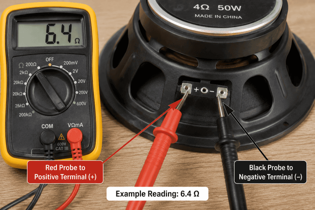
- Touch the red probe to the positive terminal of the speaker
- Touch the black probe to the negative terminal
- Read the resistance on the display
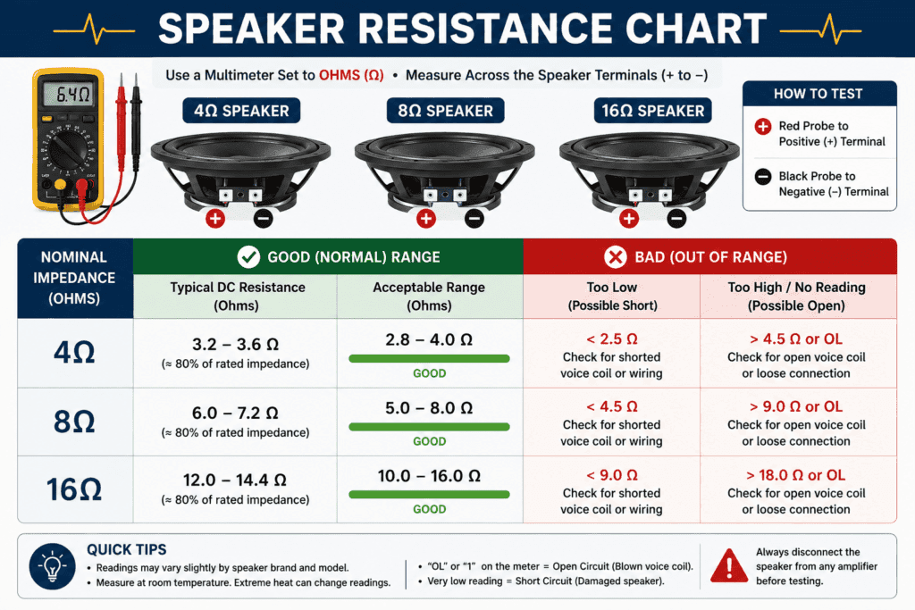
- Compare to the speaker ohm resistance chart below
📷 IMAGE RECOMMENDATION 1 Where: Inside the resistance test step by step section What: A photo showing multimeter red and black probes connected to the positive and negative terminals of a speaker Alt text: “Multimeter red and black probes connected to speaker positive and negative terminals for resistance test” Why: Shows beginners the exact probe placement on speaker terminals which vary between speaker types and brands.
Method 2: Continuity Mode Test (Quick Check)
Continuity mode gives you a fast pass or fail check. It does not measure exact resistance but tells you instantly if the voice coil is broken.
Step-by-Step Continuity Test
- Disconnect the speaker from the amplifier
- Set your multimeter to continuity mode (sound wave symbol)
- Touch one probe to each terminal; polarity does not matter in continuity mode
- Listen for the result
Beep: The voice coil has continuity; it is not open circuit. Good sign. No beep and OL: The voice coil is open circuit; the speaker is blown.
💡 Tip: Continuity mode is the fastest first check. If you hear a beep follow up with resistance mode to confirm the reading is within the expected range.
Method 3: Battery Test (No Multimeter Needed)
This is the simplest test. It tells you if the speaker cone can physically move, which confirms the voice coil is working.
Step-by-Step Battery Test
- Disconnect the speaker from the amplifier
- Take a 9V battery
- Briefly touch the positive terminal of the battery to the positive terminal of the speaker
- At the same time, touch the negative terminal of the battery to the negative terminal of the speaker
- Do this for no more than one second; do not hold the battery on the terminals
Pop sound and cone moves: Speaker is working correctly. No sound and no movement: Speaker is likely blown, or the voice coil is open.
⚠️ Warning: Do not hold the 9V battery on the speaker terminals for more than one second. DC voltage applied continuously to a speaker causes heat damage to the voice coil.
Reading Speaker Test Results
Speaker Ohm Resistance Chart
| Nominal Impedance | Good Reading | Investigate If | Bad Reading |
|---|---|---|---|
| 4Ω speaker | 2.5Ω to 3.5Ω | Below 1.5Ω or above 4Ω | OL or 0Ω |
| 8Ω speaker | 5Ω to 7Ω | Below 3Ω or above 8Ω | OL or 0Ω |
| 16Ω speaker | 12Ω to 14Ω | Below 8Ω or above 16Ω | OL or 0Ω |
What a Good Speaker Reading Looks Like
A good speaker reads a stable resistance value slightly below its nominal impedance rating. The reading should be steady without jumping or fluctuating.
What a Bad Speaker Reading Looks Like
OL (open loop): The voice coil is broken internally. No current can flow. The speaker needs replacing.
0Ω or near zero: The voice coil is shorted. Current bypasses the coil resistance completely. The speaker needs replacing.
Fluctuating or jumping reading: Intermittent connection inside the speaker. Check the flexible leads connecting the terminals to the voice coil. The speaker may need replacing.
What OL Means When Testing a Speaker
OL means open loop — there is no complete electrical path through the voice coil. In speaker testing OL means the voice coil wire has broken internally. The speaker cannot produce sound and needs to be replaced.
How to Test a Subwoofer with a Multimeter
What Is a Subwoofer?
A subwoofer is a large speaker designed specifically to reproduce low-frequency bass sounds. It uses a heavy cone and a powerful voice coil to move large amounts of air. When the voice coil fails, the subwoofer produces no bass, distorted bass, or a mechanical scraping sound.
Signs of a Blown Subwoofer
- No bass output despite the amplifier and wiring working correctly
- Buzzing, scraping, or rattling sound during bass notes
- A burnt smell coming from the subwoofer
- Cone feels stiff or stuck when pressed gently and evenly
- Visible damage to the cone or surround
Step-by-Step Subwoofer Resistance Test
- Disconnect all speaker wires from the amplifier
- For powered subwoofers, unplug the AC power cord completely
- Set your multimeter to resistance mode (Ω)
- Touch the red probe to the positive terminal and the black probe to the negative terminal
- Wait for a stable reading
- Compare to the subwoofer resistance chart below
How to Test a Dual Voice Coil Subwoofer
Dual voice coil (DVC) subwoofers have two separate voice coils — each with its own pair of terminals. Test each coil independently.
- Identify the terminals for coil 1 (marked 1+ and 1-)
- Test resistance across coil 1 terminals
- Identify the terminals for coil 2 (marked 2+ and 2-)
- Test resistance across coil 2 terminals
- Both coils should read approximately the same resistance
- A reading of OL on one coil means that coil has failed
💡 Tip: Remove any series or parallel jumper wires between the coils before testing so each coil is isolated and gives an accurate individual reading.
Subwoofer Test Results Table
| Nominal Impedance | Good DC Resistance | Bad Reading |
|---|---|---|
| 2Ω subwoofer | 1Ω to 1.8Ω | OL or 0Ω |
| 4Ω subwoofer | 2.5Ω to 3.5Ω | OL or 0Ω |
| 8Ω subwoofer | 5Ω to 7Ω | OL or 0Ω |
Mechanical Check After the Electrical Test
If the resistance reading is within the normal range but the subwoofer still sounds bad, perform this physical check:
- Place your fingertips evenly around the cone
- Press the cone inward very gently and evenly
- The movement should feel smooth with no resistance
- Any scraping, grinding, or rubbing feeling means the voice coil is rubbing inside the magnetic gap
- A cone that feels stiff or stuck indicates a damaged suspension
A scraping feeling during the physical check means mechanical damage even if the electrical test passed. The subwoofer needs professional repair or replacement.
How to Test a Tweeter with a Multimeter
Why Tweeters Test Differently
Tweeters are high-frequency speakers. Standard dome tweeters with a voice coil can be tested with a multimeter just like a regular speaker. However, piezo tweeters commonly used in guitar cabinets use a crystal element instead of a voice coil. A multimeter cannot reliably test a piezo tweeter.
Step-by-Step Tweeter Test
For standard dome tweeters:
- Disconnect the tweeter from the crossover network
- Set the multimeter to resistance mode (Ω)
- Touch one probe to each tweeter terminal
- A typical tweeter reads between 3Ω and 7Ω for an 8Ω rated tweeter
- OL means the tweeter is blown
For piezo tweeters: A multimeter test on a piezo tweeter is not reliable. The crystal element gives readings that look like a bad result even on a healthy tweeter. The best test for a piezo tweeter is to connect it to a low-volume audio signal and listen. If it produces sound, it is working.
Tweeter Test Results
| Tweeter Type | Good Reading | Bad Reading |
|---|---|---|
| Standard dome tweeter | Close to rated DC resistance | OL or 0Ω |
| Piezo tweeter | Unreliable; 5use listening test | No sound during listening test |
How to Test Speaker Polarity with a Multimeter
What Is Speaker Polarity and Why Does It Matter?
Speaker polarity refers to the correct connection of positive and negative terminals. When both speakers in a stereo pair are connected with the same polarity, they are in phase; their cones move in and out together, producing full, clear bass.
When one speaker is wired with reversed polarity, it is out of phase; the cones fight each other, causing weak, thin bass and reduced sound quality. This is a common wiring mistake that is easy to fix once diagnosed.
Step-by-Step Polarity Test
- Disconnect both speakers from the amplifier
- Set your multimeter to DC voltage mode (V—) on the lowest range
- Take a 1.5V AA battery
- Briefly touch the positive battery terminal to the red probe and the negative battery terminal to the black probe
- Quickly touch the red probe to one speaker terminal and the black probe to the other
- Watch the cone
Cone moves outward: The terminal touched by the red probe is positive (+) Cone moves inward: The terminal touched by the red probe is negative (-)
Polarity Test Results Table
| Result | What It Means |
|---|---|
| Cone moves outward on red probe terminal | That terminal is positive; mark it |
| Cone moves inward on red probe terminal | That terminal is negative; swap the probes |
| No movement | Speaker may be blown, or battery is too weak |
How to Test an Amplifier with a Multimeter
What Can a Multimeter Tell You About an Amplifier?
A multimeter can check the DC power supply voltage going into an amplifier, and the DC offset voltage at the amplifier output. It cannot fully diagnose audio performance, but it confirms whether the amplifier is receiving power and whether dangerous DC voltage is appearing at the speaker outputs.
Step-by-Step Amplifier Voltage Test
- Set your multimeter to DC voltage mode (V—)
- Locate the power supply input terminals on the amplifier
- With the amplifier powered on, touch the red probe to the positive supply rail and the black probe to the ground
- Read the voltage and compare it to the amplifier’s rated supply voltage
Step-by-Step Amplifier Output Test
- With no audio signal playing and no speakers connected
- Set your multimeter to DC voltage mode (V—)
- Touch the red probe to the positive speaker output terminal
- Touch the black probe to the negative speaker output terminal
- Read the DC offset voltage
Amplifier Test Results Table
| Test | Good Reading | Bad Reading |
|---|---|---|
| Supply voltage | Within 5% of rated supply voltage | Significantly below rated or 0V |
| DC offset at output (no signal) | Below 50mV (0.05V) | Above 100mV could damage speakers |
| DC offset at output (with signal) | Fluctuating AC voltage | Steady DC voltage: amplifier is clipping or faulty |
⚠️ Warning: A high DC offset at the amplifier output (above 1V) can permanently damage speaker voice coils. Disconnect speakers immediately if you detect significant DC voltage at the amplifier output terminals.
FAQ
What should a speaker read on a multimeter?
A speaker should read slightly below its nominal impedance rating. A 4Ω speaker should read between 2.5Ω and 3.5Ω. An 8Ω speaker should read between 5Ω and 7Ω. A 16Ω speaker should read between 12Ω and 14Ω. OL means the voice coil is open and the speaker is blown. A reading near 0Ω means the coil is shorted. Both require speaker replacement.
What does OL mean when testing a speaker?
OL means open loop — there is no complete electrical path through the voice coil. In speaker testing, OL means the voice coil wire has broken internally. The speaker cannot produce sound and needs to be replaced. OL is always a bad result when testing speaker resistance.
How do I know if my subwoofer is blown?
Signs of a blown subwoofer include no bass output, buzzing or scraping sounds during bass notes, a burnt smell, and a cone that feels stiff or stuck. Test with a multimeter set to resistance mode. A reading of OL means the voice coil is open. A reading near 0Ω means the coil is shorted. A normal resistance reading with scraping during the physical cone test means mechanical damage.
Can I test speaker polarity with a multimeter?
Yes. Use a 1.5V AA battery and touch it briefly to the speaker terminals through your multimeter probes. Watch the cone movement. If the cone moves outward the terminal connected to the positive battery side is the positive terminal. If the cone moves inward, the polarity is reversed. This test helps you correctly identify positive and negative terminals when labels are missing.
How do I test an amplifier with a multimeter?
Set your multimeter to DC voltage mode. Test the supply voltage at the amplifier’s power input terminals — it should be within 5% of the rated supply voltage. Then test the DC offset at the speaker output terminals with no signal playing — it should be below 50mV. A DC offset above 100mV at the output indicates an amplifier fault that could damage your speakers.
What is the difference between impedance and resistance in a speaker?
Impedance is the total opposition a speaker presents to an AC audio signal and changes with frequency. It is the rating printed on the speaker label (4Ω, 8Ω, 16Ω). Resistance is the opposition of the voice coil wire to DC and is what your multimeter measures. DC resistance is always slightly lower than the nominal impedance — this is completely normal.
Conclusion
Testing a speaker with a multimeter is a simple two-minute process that tells you whether the voice coil has an electrical fault.
Set your multimeter to resistance mode. Disconnect the speaker. Touch the probes to the terminals. Compare the reading to the speaker ohm resistance chart. A reading close to but slightly below the nominal impedance means the speaker is electrically healthy. OL means it is blown. Near 0Ω means it is shorted.
For a quick check, use continuity mode; a beep means the voice coil is intact. For a physical check press the cone gently; any scraping or stiffness means mechanical damage even if the electrical test passed.