Your dryer runs but produces no heat. Your water heater stopped working. Your furnace will not ignite.
Before you call a repair technician and spend hundreds of dollars, grab your multimeter. Most home appliance and HVAC failures come down to one failed component — a heating element, a coil, or a sensor. A multimeter test tells you exactly which one has failed in less than five minutes.
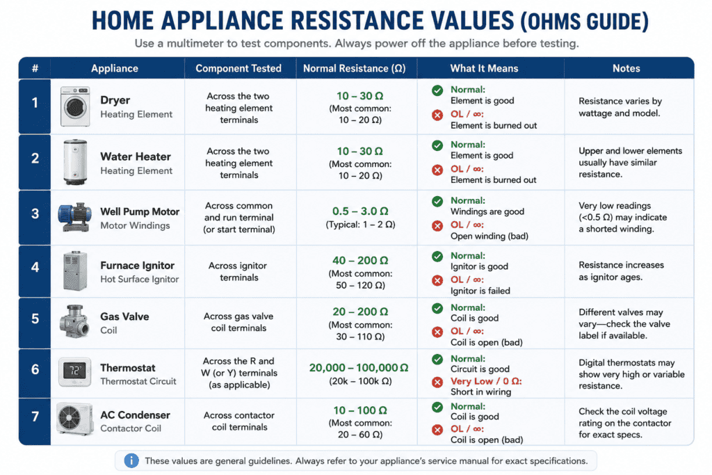
This guide covers how to test seven of the most common home appliances and HVAC components with a multimeter. Every section includes step-by-step instructions and a resistance values table so you know exactly what a good reading looks like.
Safety First: Before You Test Anything
Testing home appliances and HVAC components involves high-voltage circuits. A 240V dryer or water heater circuit can kill. Follow every safety rule in this section before touching anything.
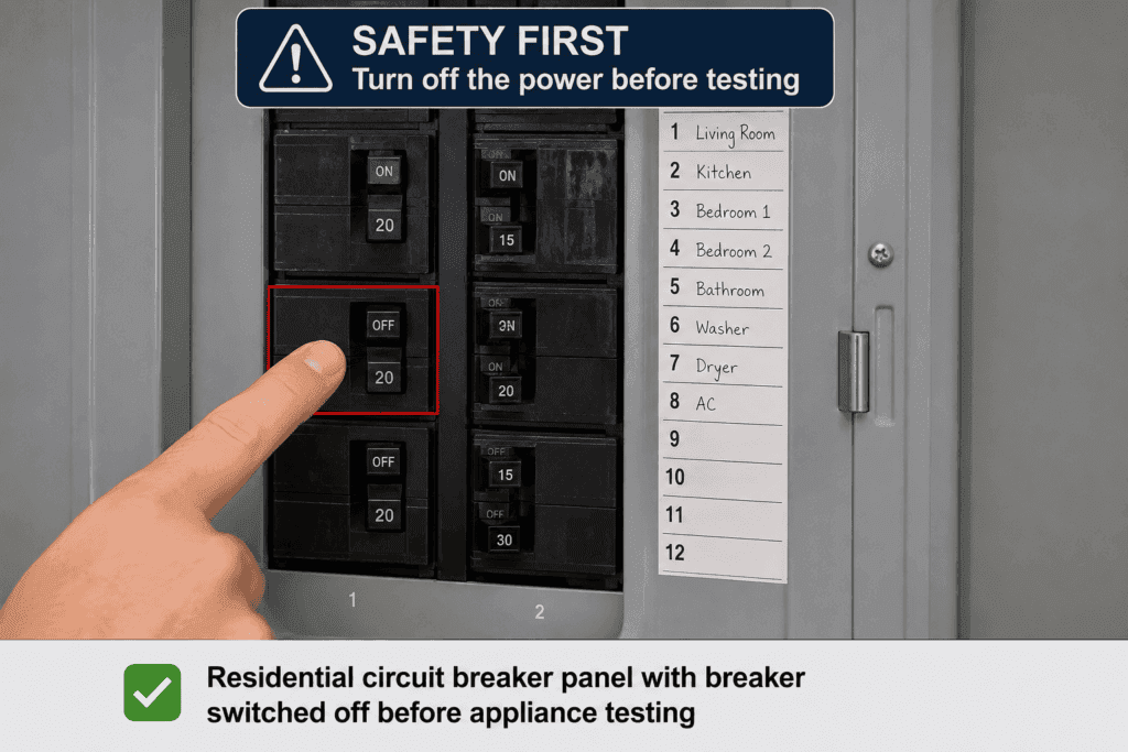
Always Turn Off the Circuit Breaker First
Before testing any appliance, go to your circuit breaker panel and switch the breaker for that appliance to the OFF position. Do not rely on the appliance power switch alone. The circuit breaker is the only way to fully cut power to the component.
After switching off the breaker, use your multimeter set to AC voltage to confirm zero voltage at the component terminals before connecting any probes. If you still see voltage, the wrong breaker was switched off.
⚠️ Warning: Never test resistance or continuity on a live circuit. Voltage in the circuit damages your multimeter and can cause serious electric shock or death.
What You Need Before You Start
- A digital multimeter with resistance mode (Ω) and continuity mode
- Red and black test leads
- A screwdriver to access component terminals
- Insulated rubber gloves
- Your appliance service manual or the component datasheet (for reference values)
How to Set Up Your Multimeter for Appliance Testing
For most tests in this article, you will use resistance mode (Ω). Here is how to set up:
- Plug the black probe into the COM port
- Plug the red probe into the VΩ port
- Turn the dial to resistance mode (Ω)
- If your multimeter is not auto-ranging, select a range of 200Ω to start
- Touch both probes together to confirm the meter reads close to 0Ω before testing
How to Test a Dryer Heating Element with a Multimeter
What Is a Dryer Heating Element?
A dryer heating element is a coiled resistance wire that heats the air inside the dryer drum. When electricity passes through the coil, it gets hot and heats the air flowing past it. When the heating element fails, the dryer runs normally but produces no heat.
Signs of a Bad Dryer Heating Element
- Dryer runs, but clothes come out cold and damp
- Dryer takes much longer than normal to dry clothes
- You can see a visible break or burn mark on the element coil
- The thermal fuse has blown (often caused by a failed heating element)
Step-by-Step Dryer Heating Element Test
- Unplug the dryer from the wall outlet completely
- Turn off the circuit breaker for the dryer as an additional safety step
- Remove the back panel of the dryer to access the heating element
- Disconnect both wires from the heating element terminals
- Set your multimeter to resistance mode (Ω)
- Touch one probe to each terminal of the heating element
- Read the resistance value on the display
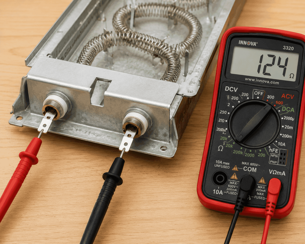
Dryer Heating Element Resistance Values Table
| Reading | What It Means | What to Do |
|---|---|---|
| 5Ω to 50Ω | Normal resistance — element is good | No replacement needed |
| OL (open loop) | Element is broken — open circuit | Replace the heating element |
| 0Ω or near zero | Element is shorted | Replace the heating element |
💡 Tip: Most electric dryer heating elements read between 8Ω and 15Ω. Gas dryers do not have a heating element — they use a gas burner assembly instead.
How to Test a Water Heater Element with a Multimeter
What Is a Water Heater Element?
An electric water heater has one or two heating elements submerged inside the water tank. These elements heat the water directly. When an element fails, the water heater stops producing hot water or produces only lukewarm water.
Signs of a Bad Water Heater Element
- No hot water or water is only lukewarm
- Hot water runs out much faster than usual
- Water heater runs constantly without reaching temperature
- Tripped breaker for the water heater circuit
Step-by-Step Water Heater Element Test
- Turn off the circuit breaker for the water heater
- Remove the access panel on the side of the water heater
- Pull back the insulation to expose the element, thermostat, and terminals
- Disconnect the wires from the element terminals
- Set your multimeter to resistance mode (Ω)
- Touch one probe to each screw terminal on the element
- Read the resistance on the display
- Also touch one probe to a terminal and one probe to the metal tank — this tests for a ground fault
Water Heater Element Resistance Values Table
| Reading | What It Means | What to Do |
|---|---|---|
| 10Ω to 30Ω | Normal resistance — element is good | No replacement needed |
| OL (open loop) | Element is burned out | Replace the element |
| 0Ω or near zero | Element is shorted | Replace the element |
| Any reading between terminal and tank | Ground fault present | Replace element immediately |
⚠️ Important: A ground fault reading between the terminal and the metal tank means the element casing has cracked and is leaking current into the water. This is a serious safety hazard. Replace the element before using the water heater.
How to Test a Well Pump with a Multimeter
What Is a Well Pump?
A well pump is a submersible or above-ground electric pump that draws water from an underground well and pushes it into your home’s plumbing system. When a well pump motor fails, the home loses water pressure or water supply entirely.
Signs of a Bad Well Pump
- No water pressure or no water at all in the home
- Pump motor hums but does not pump water
- Circuit breaker for the pump trips repeatedly
- Pump runs continuously without building pressure
Step-by-Step Well Pump Test
- Turn off the circuit breaker for the well pump
- Locate the pump control box (usually near the pressure tank)
- Disconnect the wires going to the pump motor from the control box terminals
- Set your multimeter to resistance mode (Ω)
- Test resistance between each pair of motor wires
- Also test from each wire to the ground wire to check for insulation breakdown
Well Pump Resistance Values Table
| Test | Normal Reading | Bad Reading |
|---|---|---|
| Wire to wire (motor windings) | 0.5Ω to 5Ω depending on pump size | OL or 0Ω |
| Wire to ground | OL (no connection) | Any reading indicates insulation failure |
| All three wires balanced | Readings should be similar | Very different readings indicate failed winding |
💡 Tip: Well pump resistance values vary significantly depending on pump horsepower and brand. Always check the pump datasheet for exact resistance specifications if available.
How to Test a Furnace Ignitor with a Multimeter
What Is a Furnace Ignitor?
A furnace ignitor is the component that lights the gas burner in a gas furnace. Most modern furnaces use a hot surface ignitor — a silicon carbide or silicon nitride element that glows red hot when electricity passes through it and ignites the gas. When the ignitor fails the furnace blows cold air, and the burner never lights.
Signs of a Bad Furnace Ignitor
- Furnace blower runs, but no heat is produced
- You can hear the furnace attempt to ignite, but the burner never lights
- The ignitor does not glow during startup (visible through the furnace inspection window)
- Furnace error code indicating ignition failure
Step-by-Step Furnace Ignitor Test
- Turn off the furnace power switch and the circuit breaker for the furnace
- Allow the furnace to cool completely before opening the access panel
- Locate the ignitor — it is a small, fragile element near the burners
- Disconnect the ignitor wiring connector
- Set your multimeter to resistance mode (Ω)
- Touch one probe to each terminal of the ignitor connector
- Read the resistance on the display
⚠️ Warning: Never touch the ignitor element with bare hands. The oil from your skin creates a hot spot that causes premature failure. Handle only by the ceramic base or wiring.
Furnace Ignitor Resistance Values Table
| Ignitor Type | Normal Resistance | Bad Reading |
|---|---|---|
| Silicon carbide ignitor | 40Ω to 90Ω | OL or reading outside range |
| Silicon nitride ignitor | 15Ω to 50Ω | OL or reading outside range |
| Any ignitor type | Reading within spec | OL always means replace it |
How to Test a Gas Valve with a Multimeter
What Is a Gas Valve?
A gas valve controls the flow of gas to the burners in a furnace, water heater, or dryer. It is operated by electromagnetic coils that open and close when voltage is applied. When a gas valve coil fails, the burner never receives gas, and the appliance produces no heat.
Signs of a Bad Gas Valve
- Furnace or water heater ignites, but flame goes out immediately
- No gas smell near the burner during a heating cycle
- Ignitor glows correctly, but burner never lights
- Furnace error code indicating gas valve failure
Step-by-Step Gas Valve Test
- Turn off power and gas supply to the appliance
- Locate the gas valve and identify the coil connectors
- Disconnect the coil wiring connectors from the gas valve
- Set your multimeter to resistance mode (Ω)
- Touch one probe to each terminal of each coil connector
- Read the resistance for each coil separately
Gas Valve Resistance Values Table
| Coil | Normal Resistance | Bad Reading |
|---|---|---|
| Main valve coil | 40Ω to 100Ω | OL or 0Ω |
| Pilot valve coil | 20Ω to 80Ω | OL or 0Ω |
| Any coil | Resistance within range | OL means coil is open — replace valve |
💡 Tip: Gas valve coil resistance values vary by manufacturer. Check the valve label or appliance service manual for exact specifications.
How to Test a Thermostat with a Multimeter
What Is a Thermostat?
A thermostat monitors temperature and sends signals to heating and cooling equipment to turn on or off. A faulty thermostat causes the HVAC system to behave erratically — not turning on when it should or not turning off when the set temperature is reached.
Signs of a Bad Thermostat
- HVAC system does not respond to thermostat setting changes
- Room temperature never reaches the set point
- System runs continuously without cycling off
- Display is blank or shows incorrect temperature
Step-by-Step Thermostat Test
- Turn off the HVAC system at the circuit breaker
- Remove the thermostat cover from the wall
- Disconnect the thermostat wires from the terminals
- Set your multimeter to continuity mode (sound wave symbol)
- Touch one probe to the R terminal wire and one probe to the W terminal wire (for heating)
- Manually trigger the thermostat by moving the temperature setting above room temperature
- Listen for a beep confirming continuity when the thermostat calls for heat
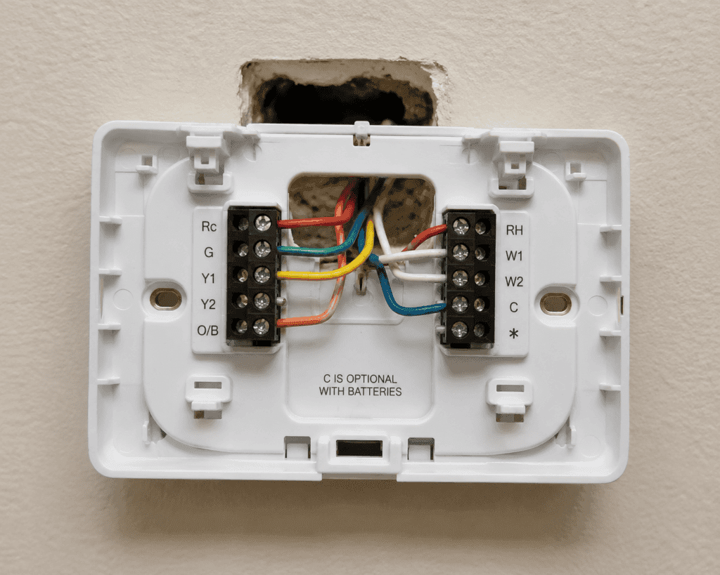
Thermostat Test Results Table
| Test | Result | What It Means |
|---|---|---|
| Continuity when calling for heat | Beep | Thermostat is switching correctly — good |
| No continuity when calling for heat | No beep | Thermostat contacts have failed — replace |
| Continuity when not calling | Beep | Thermostat is stuck closed — replace |
| Voltage at R terminal | 24V AC | Power supply to thermostat is correct |
| No voltage at R terminal | 0V | Check transformer and wiring |
How to Test a Condenser with a Multimeter
What Is a Condenser?
In HVAC systems, the condenser is the outdoor unit of an air conditioning system. It contains the compressor, condenser coil, and condenser fan motor. When the condenser fan motor fails, the unit cannot dissipate heat, and the system shuts down on high pressure. Testing the fan motor windings with a multimeter confirms whether the motor has failed.
Signs of a Bad Condenser Fan Motor
- Outdoor unit runs, but fan blade does not spin
- System trips on high pressure repeatedly
- Loud humming sound from outdoor unit with no fan movement
- Fan spins only when manually started
Step by Step Condenser Fan Motor Test
- Turn off the air conditioning system and the outdoor disconnect switch
- Remove the top panel of the outdoor unit to access the fan motor
- Locate the fan motor wiring and disconnect the motor leads from the capacitor and contactor
- Set your multimeter to resistance mode (Ω)
- Test resistance between the common wire and the run wire
- Test resistance between the common wire and the start wire
- Test each wire to the motor housing for a ground fault
Condenser Fan Motor Resistance Values Table
| Test | Normal Reading | Bad Reading |
|---|---|---|
| Common to run winding | 2Ω to 20Ω | OL or 0Ω |
| Common to start winding | 4Ω to 40Ω | OL or 0Ω |
| Run to start (sum of both) | Should equal common-run plus common-start | Very different means failed winding |
| Any wire to motor housing | OL | Any reading means ground fault |
Complete Resistance Values Table for Home Appliances
| Component | Normal Resistance Range | Bad Reading |
|---|---|---|
| Dryer heating element | 5Ω to 50Ω (typically 8Ω to 15Ω) | OL or 0Ω |
| Water heater element | 10Ω to 30Ω | OL or 0Ω |
| Well pump motor windings | 0.5Ω to 5Ω | OL or 0Ω |
| Furnace ignitor (silicon carbide) | 40Ω to 90Ω | OL |
| Furnace ignitor (silicon nitride) | 15Ω to 50Ω | OL |
| Gas valve main coil | 40Ω to 100Ω | OL or 0Ω |
| Gas valve pilot coil | 20Ω to 80Ω | OL or 0Ω |
| Condenser fan motor common to run | 2Ω to 20Ω | OL or 0Ω |
| Condenser fan motor common to start | 4Ω to 40Ω | OL or 0Ω |
FAQ
What resistance should a dryer heating element read?
A good dryer heating element reads between 5Ω and 50Ω on a multimeter set to resistance mode. Most electric dryer heating elements read between 8Ω and 15Ω. A reading of OL means the element has an open circuit and needs replacing. A reading close to 0Ω means it is shorted. Both require replacement.
How do I know if my water heater element is bad?
Set your multimeter to resistance mode. Turn off the circuit breaker and disconnect the wires from the element terminals. Touch one probe to each terminal. A good element reads between 10Ω and 30Ω. OL means the element is burned out. Also test from one terminal to the metal tank — any reading here means a ground fault, and the element must be replaced immediately.
Can I test a well pump with a basic multimeter?
Yes. A basic digital multimeter with resistance mode is enough to test well pump motor windings. Disconnect the pump wires from the control box and test resistance between each pair of wires. Normal readings are 0.5Ω to 5Ω depending on pump size. OL or 0Ω readings indicate a failed motor winding. Also test each wire to the ground wire — any reading indicates insulation breakdown.
What should a furnace ignitor read on a multimeter?
A silicon carbide hot surface ignitor reads between 40Ω and 90Ω on a multimeter. A silicon nitride ignitor reads between 15Ω and 50Ω. A reading of OL means the ignitor element is broken and needs replacing. Always handle the ignitor by the ceramic base only — never touch the element with bare hands as skin oil causes premature failure.
How do I test a gas valve with a multimeter?
Turn off power and gas to the appliance. Disconnect the coil wiring connectors from the gas valve. Set the multimeter to resistance mode and touch one probe to each terminal of each coil. A good main valve coil reads 40Ω to 100Ω. A good pilot coil reads 20Ω to 80Ω. OL on any coil means the coil has failed open circuit and the gas valve needs replacing.
What is a normal thermostat resistance reading?
Thermostat testing uses continuity mode rather than resistance mode. Set the multimeter to continuity and trigger the thermostat by raising the temperature setting above room temperature. You should hear a beep confirming the thermostat contacts are closing and calling for heat. No beep means the contacts have failed and the thermostat needs replacing.
Conclusion
A multimeter is the most useful diagnostic tool you can have for home appliance and HVAC repairs.
Before calling a technician, test the most likely failed component yourself. A dryer heating element costs $20 to $50. A water heater element costs $10 to $30. A furnace ignitor costs $15 to $50. Knowing which component has failed saves you the diagnostic fee alone.
Always turn off the circuit breaker before testing. Always confirm zero voltage before connecting probes. And always compare your resistance reading to the values table in this guide to know whether a component needs replacing.
Ready to learn more? Check out our Testing Outlets and Electrical Guide for home wiring diagnostics and our How to Use a Multimeter guide for a complete beginner overview of every multimeter function.