You plugged everything in correctly, but something is still not working. Your internet is down. Your TV has no signal. A device is not charging. An outlet is dead.
Before replacing anything, test the wire. A broken wire is one of the most common and most overlooked causes of electrical problems. And a multimeter can diagnose most wire problems in under two minutes.
This guide shows you how to test seven different types of wires and cables with a multimeter. Every section includes step-by-step instructions and a results table so you know exactly what each reading means.
What You Need Before You Start
Tools Required
- A digital multimeter with continuity mode and resistance mode
- Red and black test leads
- A short piece of known-good wire for a return cable (for some tests)
- Insulated rubber gloves for live wire testing
How to Set Up Your Multimeter for Wire Testing
Most wire tests in this guide use continuity mode. Here is how to set up:
- Plug the black probe into the COM port
- Plug the red probe into the VΩ port
- Turn the dial to continuity mode (sound wave symbol)
- Touch both probes together to confirm the meter beeps
- For resistance tests, turn the dial to the Ω symbol instead
Safety Rules for Testing Wires
⚠️ Warning: Never test resistance or continuity on a live wire. Always turn off the circuit breaker and confirm zero voltage before connecting probes for resistance or continuity tests.
For identifying hot and neutral wires, only use the AC voltage setting. Never use resistance or continuity mode on a live circuit.
Wire Color Code Table
Understanding wire colors before you test helps you connect the right probes to the right wires.
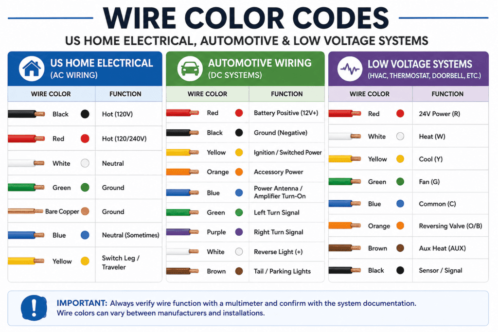
US Home Electrical Wire Colors
| Wire Color | Function | Notes |
|---|---|---|
| Black | Hot (live) | Carries current to the load |
| White | Neutral | Returns current to the panel |
| Green or bare copper | Ground | Safety earth connection |
| Red | Second hot | Used in 240V circuits |
| Blue | Hot (in conduit) | Traveler wire in 3-way switches |
Automotive Wire Colors
| Wire Color | Function |
|---|---|
| Red | Positive (12V) |
| Black | Negative (ground) |
| Yellow | Battery positive (constant) |
| Green | Right turn signal |
| White | Left turn signal |
Low Voltage Wire Colors (Ethernet, Phone, Coax)
| Cable Type | Wire Colors | Notes |
|---|---|---|
| Ethernet (RJ45) | 8 colored wires in 4 pairs | Orange, green, blue, brown pairs |
| Phone line (RJ11) | Blue, orange, green, brown | Tip and ring pairs |
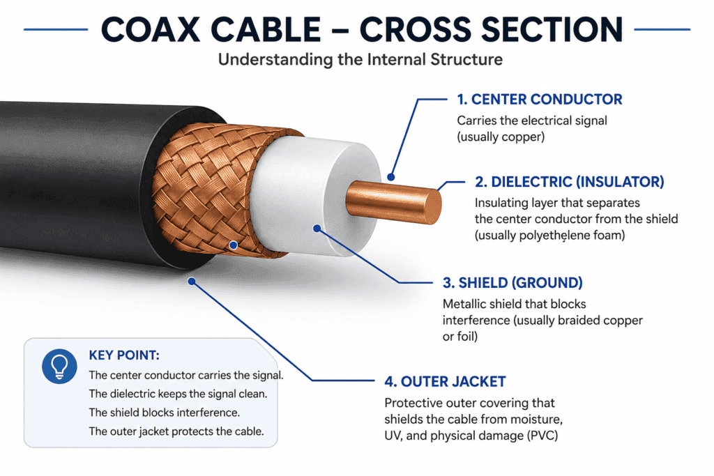
| Coax | Single center conductor plus shield | Center is signal, shield is ground |
How to Test Wire Continuity with a Multimeter
What Is Wire Continuity?
Continuity means there is a complete unbroken path for current to flow through a wire from one end to the other. A wire with continuity is intact. A wire without continuity has an internal break somewhere along its length.
The outside of a wire can look perfect while the copper inside is broken. Continuity testing reveals internal breaks that visual inspection misses completely.
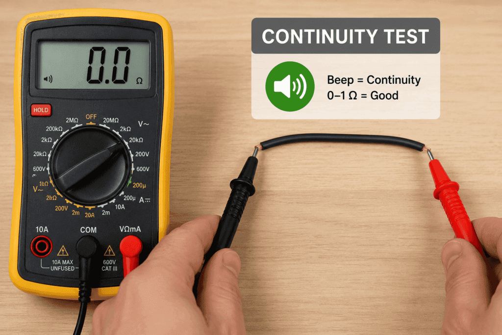
Step by Step Continuity Test for Wires
- Turn off all power to the circuit
- Disconnect the wire from all components at both ends
- Set your multimeter to continuity mode (sound wave symbol)
- Touch the red probe to one end of the wire
- Touch the black probe to the other end of the same wire
- Listen for the result
Wire Continuity Test Results Table
| Result | What It Means | What to Do |
|---|---|---|
| Beep | Wire is intact — continuity confirmed | Wire is good to use |
| No beep — OL | Wire has an internal break | Replace the wire |
| Beep only sometimes | Intermittent break — loose connection inside | Replace the wire |
What to Do If a Wire Fails the Continuity Test
If the wire fails the continuity test it has an internal break and needs replacing. Do not try to repair a broken wire inside a wall — always replace the full run. For extension cords and appliance cables, a failed continuity test means the cord needs to be replaced immediately for safety.
How to Identify Hot and Neutral Wires with a Multimeter
Why Identifying Wires Matters
In older homes, wiring colors are sometimes inconsistent. Wires may be painted, covered in tape, or simply not labeled. Incorrectly identifying a hot wire as neutral creates a serious shock and fire hazard.
A multimeter set to AC voltage is the safe and accurate way to identify which wire is hot and which is neutral before working on a circuit.
Step by Step Hot and Neutral Wire Identification
- Set your multimeter to AC voltage mode (V~)
- Select the 200V range or use auto-range
- Keep the circuit live for this test only
- Touch the black probe to a known ground (bare copper wire or ground screw)
- Touch the red probe to the first unknown wire
- Read the voltage on the display
- Repeat for each unknown wire
What the Readings Mean
| Reading | Wire Type |
|---|---|
| 110V to 125V AC | Hot wire — carries live current |
| 0V | Neutral or ground wire |
| Any reading between neutral and ground | Possible wiring fault — investigate further |
⚠️ Important: Always switch back to resistance or continuity mode and turn off the circuit breaker before doing any further work on the wiring after identification.
How to Test Wire Polarity with a Multimeter
What Is Wire Polarity?
Polarity refers to the correct connection of positive and negative (or hot and neutral) wires. Reversed polarity means the hot and neutral wires have been swapped. This is dangerous — devices may appear to work, but shock hazards exist even when a switch is in the off position.
Step-by-Step Polarity Test
- Set the multimeter to AC voltage (V~)
- Insert the red probe into the small right slot of an outlet (hot)
- Insert the black probe into the large left slot (neutral)
- Read the voltage — should be 110V to 125V
- Now swap the probes
- If you still get a voltage reading, the outlet has reversed polarity
Polarity Test Results Table
| Test | Normal Reading | Reversed Polarity |
|---|---|---|
| Red to hot / Black to neutral | 110V to 125V | 0V or very low |
| Red to neutral / Black to hot | 0V | 110V to 125V |
💡 Tip: For a complete outlet polarity and grounding test check out our Testing Outlets Guide.
How to Test a Coax Cable with a Multimeter
What Is a Coax Cable?
A coaxial cable has two conductors — a center conductor carrying the signal and an outer shield surrounding it. The shield blocks electromagnetic interference and keeps the signal clean. Coax cables are used for TV, satellite, internet, and CCTV systems.
What a Multimeter Can and Cannot Tell You About Coax Cable
This is important to understand before testing. A multimeter can confirm:
- Whether the center conductor is broken (continuity test)
- Whether the shield is broken (continuity test)
- Whether the center conductor is shorted to the shield (short circuit test)
A multimeter cannot detect:
- Signal quality problems
- Partial shield damage that still passes current
- Interference or noise issues
- Impedance mismatches
For full coax signal testing, you need a dedicated coax cable tester or signal meter.
Step-by-Step Coax Cable Continuity Test
- Disconnect the coax cable from all devices at both ends
- Set your multimeter to continuity mode
- At one end of the cable, connect a short wire (return cable) between the center conductor and the outer shield
- At the other end, touch the red probe to the center conductor pin
- Touch the black probe to the outer shield connector
- Listen for a beep confirming continuity through both conductors
Step-by-Step Coax Cable Short Circuit Test
- With the cable disconnected at both ends and no return wire connected
- Set your multimeter to continuity mode
- Touch the red probe to the center conductor at one end
- Touch the black probe to the outer shield at the same end
- Listen for the result
Coax Cable Test Results Table
| Test | Good Result | Bad Result |
|---|---|---|
| Continuity test (with return cable) | Beep | No beep — cable is broken |
| Short circuit test (center to shield) | No beep — OL | Beep means cable is shorted |
| Shield continuity (end to end) | Beep | No beep — shield is broken |
When to Use a Dedicated Coax Tester Instead
If the continuity test passes but you still have TV or internet signal problems, the issue is signal quality — not a broken wire. Use a dedicated coax signal tester or contact your service provider. A multimeter cannot diagnose signal level or frequency problems.
How to Trace an Ethernet Cable with a Multimeter
What Is an Ethernet Cable?
An Ethernet cable (RJ45) carries network data between computers, routers, and switches. It contains 8 wires in 4 color-coded pairs. Testing Ethernet continuity with a multimeter is more time-consuming than using a dedicated cable tester, but it works for basic pass or fail checks.
Step-by-Step Ethernet Cable Continuity Test
- Disconnect the Ethernet cable from all devices
- Set your multimeter to continuity mode
- At the far end of the cable, create a loopback by connecting Pin 1 to Pin 2 using a short wire
- At the near end, touch the red probe to Pin 1 and the black probe to Pin 2
- A beep confirms continuity through both wires
- Repeat for all 4 pairs (Pins 1-2, 3-6, 4-5, 7-8)
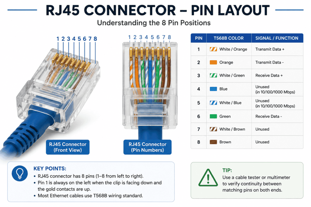
Ethernet Cable Test Results Table
| Test | Good Result | Bad Result |
|---|---|---|
| Each wire pair continuity | Beep on all 4 pairs | No beep on any pair means that pair is broken |
| All 8 pins test | All pairs beep | Missing beep identifies broken pair |
💡 Tip: For a faster and more complete Ethernet cable test use a dedicated RJ45 cable tester. These cost around $10 and test all 8 wires simultaneously with LED indicators. See our Continuity Testing Guide for more details.
How to Test a Phone Line with a Multimeter
What Is a Phone Line Cable?
A phone line cable uses an RJ11 connector with 2 to 4 wires. The active pair for standard telephone service is the blue and white-blue wires (Tip and Ring). Testing a phone line cable confirms whether the wiring between the wall jack and the distribution point is intact.
Step-by-Step Phone Line Test
- Disconnect the phone line cable from both ends
- Set your multimeter to continuity mode
- At the far end, connect the blue wire to the white-blue wire using a short jumper
- At the near end, touch one probe to the blue wire terminal and one probe to the white-blue terminal
- A beep confirms the active pair is intact
Phone Line Test Results Table
| Result | What It Means |
|---|---|
| Beep | Active pair is intact — cable is good |
| No beep | Active pair has a break — replace cable |
| Voltage reading on active pair | Line is live — disconnect from wall before testing |
⚠️ Warning: Always disconnect the phone line from the wall jack before testing. An active phone line carries 48V DC and up to 90V AC during ringing. This can damage your multimeter.
How to Test a USB Cable with a Multimeter
What Is a USB Cable?
A USB cable carries both power and data between devices. It contains four wires — two for power (5V positive and ground) and two for data (D+ and D-). A failed USB cable often charges a device but transfers no data, or charges very slowly because the power wires are damaged.
Step-by-Step USB Cable Test
- Set your multimeter to continuity mode
- Use pin-out diagrams for your USB type (USB-A, USB-C, Micro USB) to identify pin positions
- Test continuity between Pin 1 (5V power) on the plug end and Pin 1 on the socket end
- Test continuity between Pin 4 (ground) on the plug end and Pin 4 on the socket end
- Test continuity on the data pins (Pin 2 D- and Pin 3 D+)
USB Cable Test Results Table
| Wire | Good Result | Bad Result |
|---|---|---|
| Pin 1 (5V power) | Beep | No beep — power wire is broken |
| Pin 4 (Ground) | Beep | No beep — ground wire is broken |
| Pin 2 (D-) | Beep | No beep — data wire broken |
| Pin 3 (D+) | Beep | No beep — data wire broken |
| Power pins to data pins | No beep | Beep means short circuit |
💡 Tip: A USB cable that charges but does not transfer data usually has broken D+ or D- wires while the power wires are still intact.
Common Wire Testing Mistakes Beginners Make
Testing a Live Wire in Resistance Mode
Never measure resistance or continuity on a live wire. The voltage in the circuit gives false readings and can permanently damage your multimeter. Always turn off the circuit breaker and confirm zero voltage before switching to resistance or continuity mode.
Not Using a Return Cable for Continuity Tests
For continuity testing on a long wire where both ends are far apart, you need a return cable — a known-good wire that connects the two conductors at the far end. Without a return cable, you cannot complete the test circuit and the multimeter cannot detect continuity.
Confusing Wire Colors Between Systems
Wire colors mean different things in different systems. A black wire in home electrical wiring is hot and dangerous. A black wire in automotive wiring is the negative ground. A black wire in low-voltage speaker wiring may be the negative signal. Always confirm which system you are working with before connecting probes.
FAQ
How do I know if a wire is broken?
Set your multimeter to continuity mode and touch one probe to each end of the wire. A beep means the wire is intact. No beep and an OL reading means there is an internal break. The outside of the wire may look fine — copper wire can break internally without any visible damage to the insulation.
Can I test a coax cable with a basic multimeter?
Yes, but with limitations. A multimeter can confirm whether the center conductor and shield have continuity and whether there is a short circuit between them. However, a multimeter cannot detect signal quality problems, partial shield damage, or impedance issues. For full coax signal testing, use a dedicated coax tester or signal meter.
How do I identify a hot wire with a multimeter?
Set your multimeter to AC voltage mode (V~). Touch the black probe to a known ground and the red probe to the unknown wire. A reading of 110V to 125V (in the US) means the wire is hot. A reading of 0V means it is neutral or ground. Always keep the circuit live only for this specific voltage identification test.
What does OL mean when testing a wire?
OL means open loop — there is no complete path for current to flow. When testing wire continuity, OL means the wire has an internal break and needs replacing. When testing for a short circuit between coax center and shield, OL is the good result — it means no short exists.
How do I test an Ethernet cable without a cable tester?
Disconnect the cable from both ends. Set your multimeter to continuity mode. At the far end, create a loopback by connecting Pin 1 to Pin 2 with a short wire. At the near end, test continuity between Pin 1 and Pin 2. Repeat for all 4 pairs. A beep on all pairs means the cable is good. No beep on any pair identifies the broken wires.
What is the difference between continuity and resistance testing for wires?
Continuity testing gives you a simple yes or no answer with a beep. It tells you whether a wire is intact or broken. Resistance testing gives you a specific number in ohms showing exactly how much resistance the wire has. For basic wire testing, continuity mode is faster and easier. Resistance mode is useful when you need to compare wire resistance values or check for partial damage that increases resistance without fully breaking the wire.
Conclusion
Testing wires with a multimeter is one of the most practical skills any homeowner or DIY enthusiast can have.
Continuity mode tells you instantly whether a wire is broken or intact. AC voltage mode identifies hot and neutral wires safely. Resistance mode gives you exact values for comparison.
For coax cables, remember that a multimeter confirms continuity and short circuits but cannot diagnose signal quality. For Ethernet cables a dedicated cable tester is faster, but a multimeter works for basic pass-or-fail testing.
Always turn off the circuit breaker before testing resistance or continuity. Always confirm zero voltage before touching any wires. And always check the wire color code table before connecting probes to make sure you are testing the right conductors.
Ready to go deeper? Check out our Continuity Testing Guide for a full breakdown of how continuity testing works, and our Testing Outlets Guide for home wiring diagnostics.